Radial variable plunger pump

A variable plunger and plunger technology, applied in the field of radial variable plunger pump, can solve the problems of difficulty, large lateral force, large friction between the plunger and the cylinder hole, etc., to achieve the effect of convenient flow adjustment

Inactive Publication Date: 2021-08-17
深圳市科斯腾液压设备有限公司
View PDF0 Cites 0 Cited by
  • Summary
  • Abstract
  • Description
  • Claims
  • Application Information

AI Technical Summary

Problems solved by technology

At present, the transmission mode adopted by the radial plunger hydraulic pump has the defect of large lateral force, large friction between the plunger and the cylinder hole, serious wear between the plunger and the cylinder hole, and the The ov

Method used


Image

  • Radial variable plunger pump
  • Radial variable plunger pump
  • Radial variable plunger pump

Examples


Embodiment Construction

[0025] The following description serves to disclose the present invention to enable those skilled in the art to carry out the present invention. The preferred embodiments described below are only examples, and those skilled in the art can devise other obvious variations.

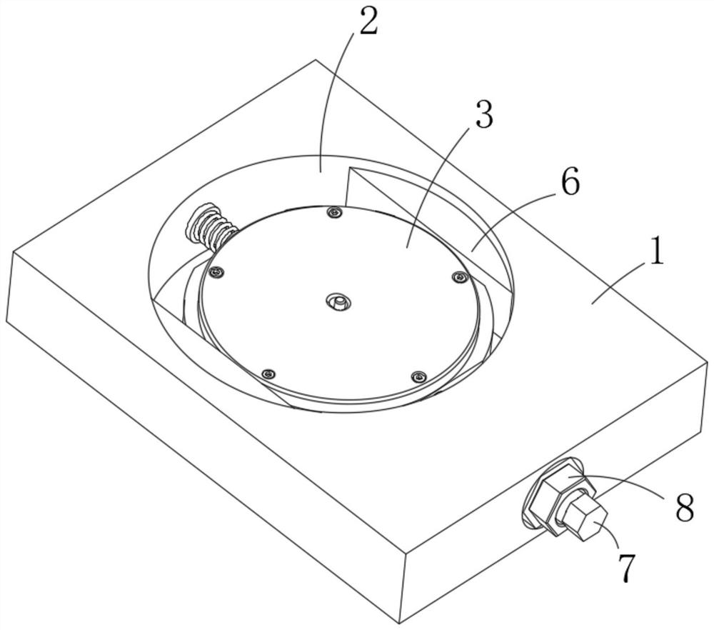
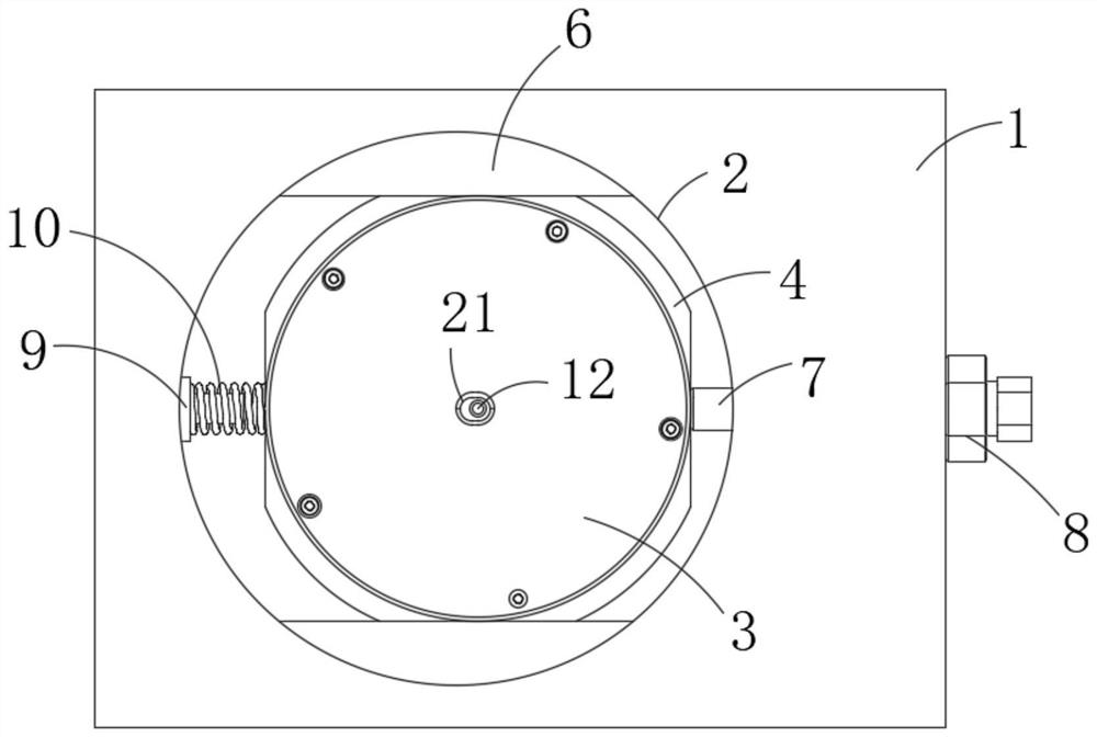
[0026] like Figure 1-Figure 5 The radial variable plunger pump shown includes a housing base 1, an inlet 2 penetrating through the upper end surface of the housing base 1, and a pump mechanism slidingly arranged inside the inlet 2 along a straight line, wherein:

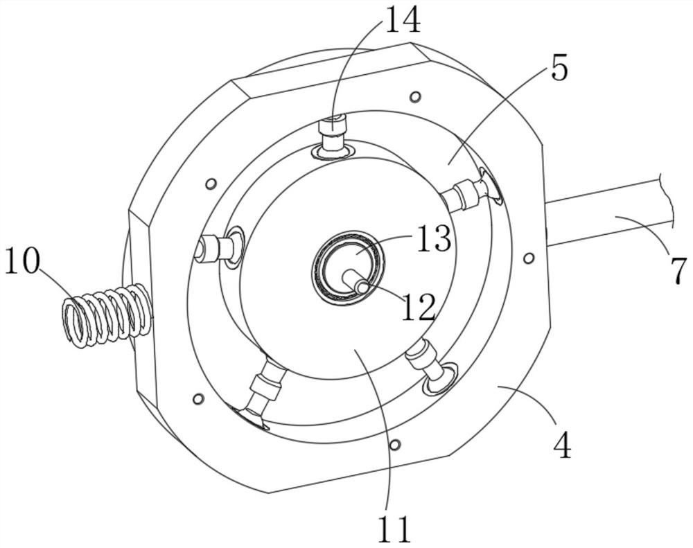
[0027] The pump mechanism includes a pump stator, a rotor 11 arranged inside the pump stator and moving along a circular trajectory, a plunger that is movably connected between the edge of the rotor 11 and the inner wall of the pump stator, and the transmission shaft that drives the rotor 11 passes through the upper end surface of the pump stator Afterwards, it is connected with external power equipment;

[0028] The pump mechanism slides along ...


PUM


Abstract

The invention relates to the field of plunger pumps, in particular to a radial variable plunger pump, which comprises a shell seat, a putting-in opening arranged on the upper end face of the shell seat in a penetrating mode and a pump mechanism arranged on the inner side of the putting-in opening in a sliding mode in the linear direction, wherein the pump mechanism comprises a pump stator, a rotor which is arranged on the inner side of the pump stator and moves along a circular track, and a plunger part which is movably connected between the edge of the rotor and the inner wall of the pump stator, and a transmission shaft part for driving the rotor penetrates through the upper end face of the pump stator and then is connected with external power equipment; and the pump mechanism slides on the inner side of the putting-in opening in the linear direction, so that the eccentric distance between the inner wall of the stator and the rotor is changed, the pulling or pushing distance of the plunger part is changed at the same time, the service life of the plunger pump is prolonged, and flow adjustment is more convenient.

Description

technical field [0001] The invention relates to the field of plunger pumps, in particular to a radially variable plunger pump. Background technique [0002] Piston pumps are widely used in high-pressure hydraulic systems, which have the advantages of high rated pressure, high efficiency, long life, and light weight per unit power. According to the different arrangements of the plunger in the cylinder, the plunger pump is divided into a radial plunger pump and an axial plunger pump. At present, the transmission mode adopted by the radial plunger hydraulic pump has the defect of large lateral force, large friction between the plunger and the cylinder hole, serious wear between the plunger and the cylinder hole, and the The overturning moment is generated on the pump, which has an adverse effect on the mechanical performance of the pump; secondly, for the radial piston type, it is difficult to adjust the flow rate, so we propose a radial variable piston pump. Contents of the...

Claims


Application Information

Patent Timeline
IPC IPC(8): F04B1/053F04B1/0465F04B1/0408F04B1/0404F04B1/07
CPCF04B1/0404F04B1/0408F04B1/0465F04B1/053F04B1/07
Inventor 朱跃龙王学国杨皓安高成徐彦周文丰杨洋陈亮
Owner 深圳市科斯腾液压设备有限公司
Why Eureka
Try Eureka