Anti-blocking hydraulic two-way slurry pump for oil exploitation

An oil extraction and anti-clogging technology, which is applied to the components of pumping devices for elastic fluids, piston pumps, and variable displacement pumps, etc. running effect

Active Publication Date: 2021-08-17
山东高原油气装备有限公司
View PDF10 Cites 1 Cited by
  • Summary
  • Abstract
  • Description
  • Claims
  • Application Information

AI Technical Summary

Problems solved by technology

[0004] Based on this, it is necessary to address the above problems and propose a hydraulic two-way mud pump that can effectively extract the mud, separate and push out the mud particles, and prevent the mud particles from clogging the equipment, so as to solve the above problems. The mud in the existing processing method proposed in the background technology is easy to block the equipment and reduce the problem of oil extraction efficiency

Method used


Image

  • Anti-blocking hydraulic two-way slurry pump for oil exploitation
  • Anti-blocking hydraulic two-way slurry pump for oil exploitation
  • Anti-blocking hydraulic two-way slurry pump for oil exploitation

Examples


Embodiment 1

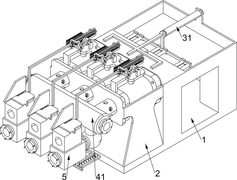
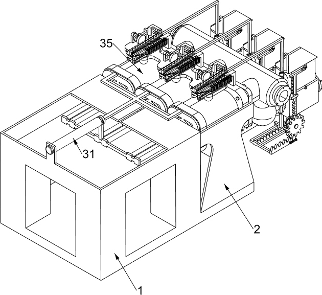
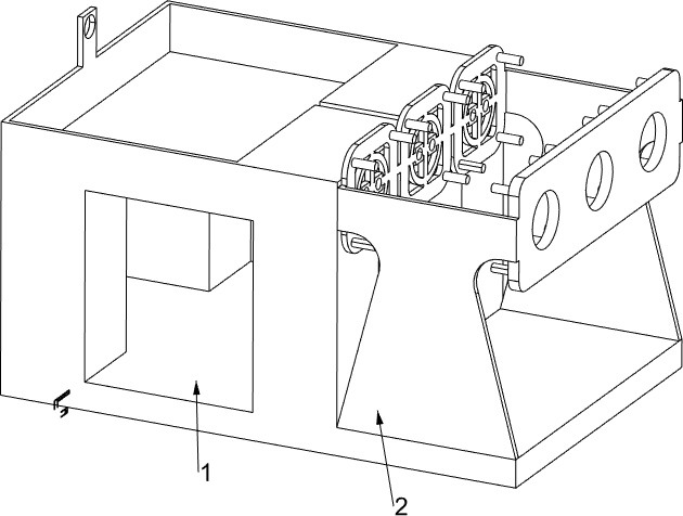
[0037] A hydraulic two-way mud pump used for anti-clogging in oil production, such as Figure 1-7 As shown, it includes a cavity chassis 1, a special-shaped connecting frame 2, a reciprocating pumping mechanism 3, a one-way conduction mechanism 4, and an anti-blocking mechanism 5. The left side of the cavity chassis 1 is fixedly connected with a special-shaped connecting frame 2, and the special-shaped connection The frame 2 is provided with a reciprocating pumping mechanism 3, the reciprocating pumping mechanism 3 is located above the cavity chassis 1, the left side of the special-shaped connecting frame 2 is fixedly connected with a one-way conduction mechanism 4, and the left part of the one-way conduction mechanism 4 is provided with Anti-clogging mechanism5.

[0038] The reciprocating pumping mechanism 3 includes an electro-hydraulic push rod 31, a triangular push rod 32, a special-shaped connecting plate 33, a piston body 34, and a piston rod 35. 31 is fixedly connected...

Embodiment 2

[0043] On the basis of Example 1, such as Figure 8-14 As shown, a rotating mechanism 6 is also included, and the rotating mechanism 6 is located above the special-shaped connecting frame 2. The rotating mechanism 6 includes an L-shaped opening support frame 61, a push ball rod 62, a third return spring 63, a rectangular slotted frame 64, Round head shaft frame 65, dial 66 and cam 67, the top of piston rod 35 is fixedly connected with L-shaped opening support frame 61, and the L-shaped opening support frame 61 is slidably connected with three push rods 62, which promotes the ball rod 62. A third return spring 63 is connected between the L-shaped opening support frame 61, the third return spring 63 is used to drive and push the club 62 to reset, and the top of the push club 62 is fixedly connected with a rectangular slot for driving the dial 66 to rotate Frame 64, three round head rotating shaft frames 65 are fixedly connected on the L-shaped opening support frame 61, and the r...

Embodiment 3

[0048] On the basis of Example 2, such as Figure 15-16As shown, a mud pushing mechanism 9 is also included, and the mud pushing mechanism 9 is located below the anti-clogging mechanism 5. The mud pushing mechanism 9 includes a T-shaped slotted frame 91, a special-shaped pushing plate 92, a first return spring 93, a sliding rack Frame 94, the second homing spring 95, double-sided wedge block 96, the 3rd homing spring 97, L-type rotating shaft frame 98, gear one 99, gear two 910, mobile rack frame 911, movable gear block 912 and the fourth Returning spring 913, T-shaped slotted frame 91 is fixedly connected to the bottom of chamber communication valve 51, and special-shaped push plate 92 is slidably connected to T-shaped slotted frame 91, between T-shaped slotted frame 91 and special-shaped push plate 92 Fixedly connected with a first return spring 93, the first return spring 93 is used to drive the special-shaped push plate 92 to reset, and the cavity communication valve 51 is...


PUM


Abstract

The invention relates to the field of oil exploitation, in particular to an anti-blocking hydraulic two-way slurry pump for oil exploitation. The anti-blocking hydraulic two-way slurry pump comprises a cavity bottom frame, a special-shaped connecting frame, a reciprocating pressure pumping mechanism, a one-way communication mechanism, an anti-blocking mechanism and the like; the left side of the cavity bottom frame is fixedly connected with the special-shaped connecting frame, the special-shaped connecting frame is provided with the reciprocating pressure pumping mechanism, and the reciprocating pressure pumping mechanism is located above the cavity bottom frame; and the left side of the special-shaped connecting frame is fixedly connected with the one-way communication mechanism, and the left portion of the one-way communication mechanism is provided with the anti-blocking mechanism. When slurry is filtered through a filter plate, the slurry meeting the requirement immediately passes through the filter plate, residual slurry particles which do not meet the requirement can be remained at the bottom of a perforated pressing frame, and therefore, the slurry particles can be conveniently pushed away by equipment subsequently, so that the situation that the oil exploitation efficiency is affected due to the fact that the equipment stops running due to the fact that the interior of a cavity communicating valve is blocked is avoided.

Description

technical field [0001] The invention relates to the field of oil exploitation, in particular to a hydraulic two-way mud pump used for anti-clogging in oil exploitation. Background technique [0002] Oil extraction is the construction of a complete oil and gas collection, separation, treatment, metering, storage, and transportation process technology on the oil field, so that the mixed fluids such as oil, gas, and water produced in the oil well can be separated and preliminarily treated, and as much as possible can be obtained. Oil and gas products and water can be reinjected or utilized to prevent environmental pollution. In order to reduce ineffective loss, oil and gas can be raised by relying on the energy self-spraying of the formation, or by artificially supplemented energy such as oil well pumps and gas lifts. The mud returned from the bottom of the well generally needs to be treated by mud purification equipment at all levels. Remove the solid phase content to prevent...

Claims


Application Information

Patent Timeline
Patent Type & Authority Applications(China)
IPC IPC(8): F04B15/02F04B17/00F04B9/10F04B53/20F04B53/00
CPCF04B9/10F04B15/02F04B17/00F04B53/00F04B53/20
Inventor 薛鹏潜凌韩涛
Owner 山东高原油气装备有限公司
Why Eureka
Try Eureka