Automatic production line monitoring system and method based on visual capture
A technology for visual capture and monitoring systems, applied in CCTV systems, components of TV systems, components of color TVs, etc., can solve problems such as low efficiency, easy deformation or damage of edges and tanks, etc.
- Summary
- Abstract
- Description
- Claims
- Application Information
AI Technical Summary
Problems solved by technology
Method used
Image
Examples
Embodiment 1
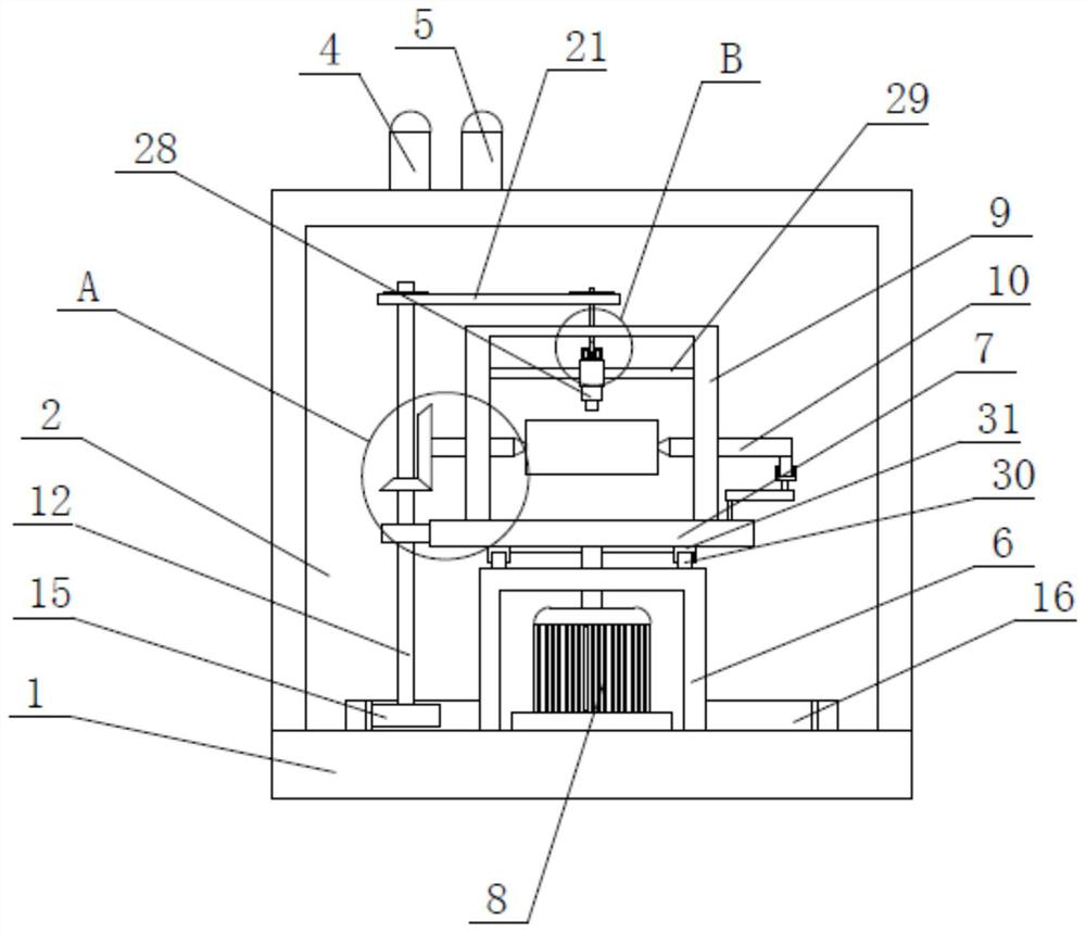
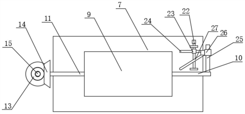
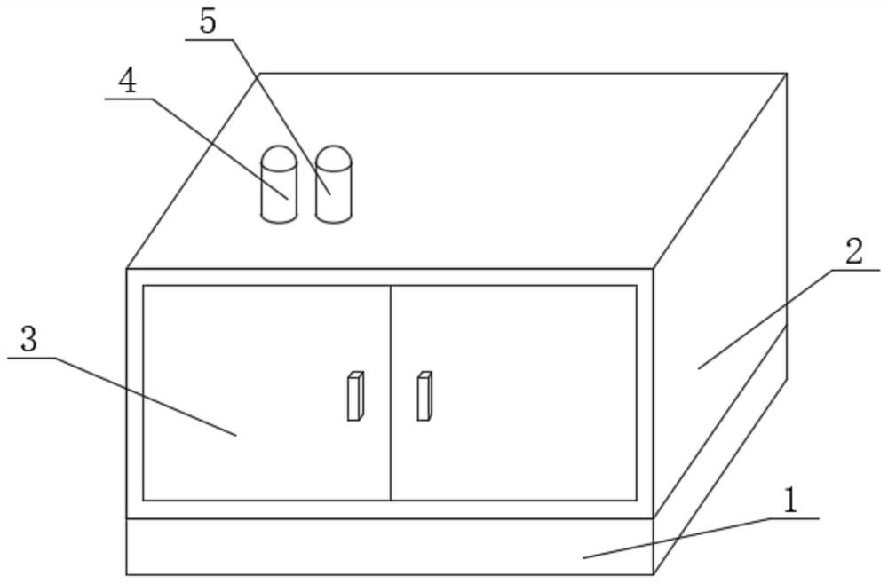
[0039] refer to Figure 1-8 In this embodiment, a production line automation monitoring system based on visual capture is proposed, including a bottom plate 1, a box body 2 is fixedly installed on the top of the bottom plate 1, and two door panels 3 are symmetrically hinged on one side of the box body 2, and the bottom plate 1 The top of the support plate 7 is rotatably connected to the support plate 7 located in the box body 2, the top of the support plate 7 is fixedly installed with a mounting frame 9, and the inner walls on both sides of the mounting frame 9 are respectively slidably connected with a positioning probe 10 and a driving probe rotatably connected with it. 11. The ends of the positioning probe 10 and the driving probe 11 that are close to each other are clamped with the same can, and the ends of the positioning probe 10 and the driving probe 11 that are far away from each other extend to both sides of the mounting frame 9 respectively, and the driving probe 11 ...
Embodiment 2
[0043] refer to Figure 8 , the present invention also proposes a production line automation method based on vision capture, including the described production line automation monitoring system based on vision capture, and also includes the following steps:
[0044] S1: Firstly, the pop can to be detected is placed between the positioning probe 10 and the driving probe 11, and then the rotatable screw 22 drives the positioning probe 10 to move laterally until it cooperates with the driving probe 11. Carry out clamping positioning;
[0045] S2: Start the driving motor 8 to drive the support plate 7 to rotate, and at this time, it will drive the rotating shaft 12 to perform circular motion, and the rotating shaft 12 can also rotate while performing circular motion. At this time, use the static friction between the driving probe 11 and the can The force can drive the can to rotate;
[0046] S3: When the rotating shaft 12 rotates, the transmission belt 21 can drive the Z-shaped ...
PUM
 Abstract
Description
Claims
Application Information
 - R&D
- Intellectual Property
- Life Sciences
- Materials
- Tech Scout
- Unparalleled Data Quality
- Higher Quality Content
- 60% Fewer Hallucinations
Browse by: Latest US Patents, China's latest patents, Technical Efficacy Thesaurus, Application Domain, Technology Topic, Popular Technical Reports.
© 2025 PatSnap. All rights reserved.Legal|Privacy policy|Modern Slavery Act Transparency Statement|Sitemap|About US| Contact US: help@patsnap.com


