Method for realizing automatic generation of transmission equipment system diagram

A technology for automatic generation and transmission of equipment, applied in 2D image generation, image data processing, instruments, etc., can solve the problems of high work intensity, strong repeatability, high error rate, etc., to reduce work intensity, reduce error rate, and facilitate The effect of self-test and error correction

Active Publication Date: 2021-08-17
GUANGZHOU TIANYUE ELECTRONICS TECH
View PDF7 Cites 0 Cited by
  • Summary
  • Abstract
  • Description
  • Claims
  • Application Information

AI Technical Summary

Problems solved by technology

[0004] The present invention provides a method for automatically generating transmission equipment system diagrams, which solves the problem that most of the current transmission equipment system diagrams are drawn manually, and the work intensity is high. Highly repetitive mechanical work with a high error rate

Method used


Image

  • Method for realizing automatic generation of transmission equipment system diagram
  • Method for realizing automatic generation of transmission equipment system diagram

Examples


Embodiment Construction

[0024] The present invention will be further described below in conjunction with the accompanying drawings and embodiments.

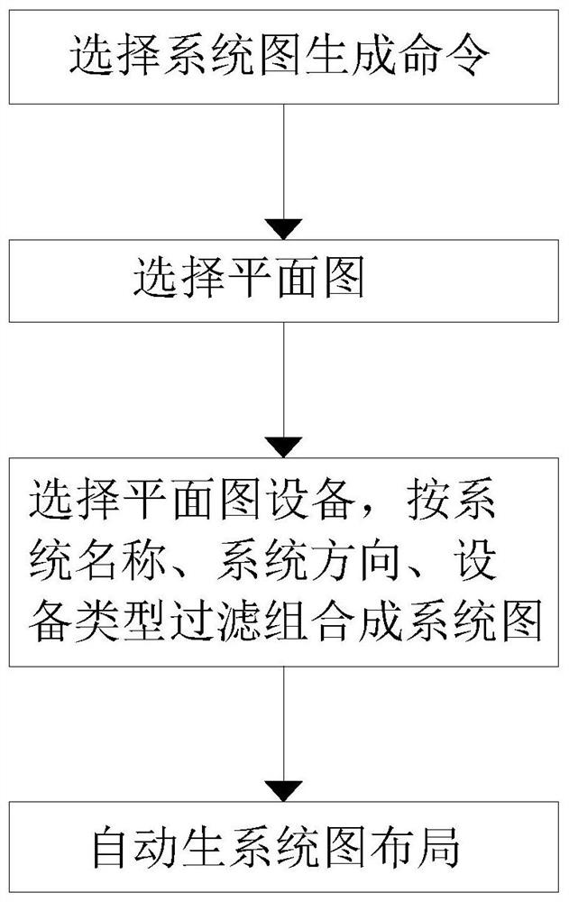
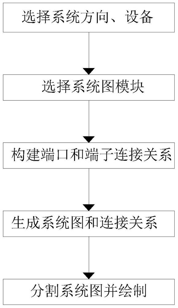
[0025] Please refer to figure 1 and figure 2 ,in figure 1 It is a flow chart of the steps of a preferred embodiment of the method for realizing the automatic generation of the transmission equipment system diagram provided by the present invention; figure 2 for figure 1 Shown is a flowchart of a method for automatically generating a system diagram of a transmission device. The method for realizing the automatic generation of the transmission equipment system diagram includes the following steps:

[0026] Step 1: The designer pre-selects the system diagram generation command, and then generates the equipment rack panel diagram;

[0027] Step 2: Then the user selects the floor plan option, and then the panel diagram of the equipment rack is regenerated into the ODF terminal panel diagram;

[0028] Step 3: Then the designer establishes the connecti...


PUM


Abstract

The invention provides a method for realizing automatic generation of a transmission equipment system diagram, which comprises the following steps of: 1, pre-selecting a system diagram generation command by a designer, and then generating an equipment group frame panel diagram; 2, selecting a planar graph option by a user, and generating an ODF terminal panel graph from the equipment group frame panel graph; and 3, then enabling a designer to establishes a connection relationship between equipment ports and a connection relationship between the equipment ports and the ODF terminals. According to the method, a designer can construct a data structure according to the connection relationship between the equipment board card port and the ODF terminal through the step flow matching of the step 1, the step 2, the step 3, the step 4 and the step 5, and then draws a connecting line and sets the information of the port and the terminal in a drawing according to the data structure, and when the connection relationships are many, the generated system diagram is very large, at the moment, according to the size of a picture frame, a system picture and a connection relation are automatically segmented through an algorithm, and drawing is performed in a drawing according to a sequence;.

Description

technical field [0001] The invention relates to the field of drawing production of communication transmission equipment, in particular to a method for automatically generating system diagrams of transmission equipment. Background technique [0002] Communication engineering project transmission equipment system diagram According to different systems, the system diagram is divided into many types. The system diagram of different systems has different drawing methods. When drawing the system diagram, it is necessary to draw the connection between the equipment board and the ODF terminal, and write the board Card numbers and terminal numbers are time-consuming, error-prone, and costly for inspection and review. At present, the drawing of transmission equipment system diagrams basically requires designers to manually draw a template, then apply the template, and then update the template data. However, the system diagrams generated by each office corresponding to different proj...

Claims


Application Information

Patent Timeline
Patent Type & Authority Applications(China)
IPC IPC(8): G06T11/20G06F21/32G06F21/46
CPCG06T11/206G06F21/32G06F21/46
Inventor 褚振鲁谢敏理陈袁霞
Owner GUANGZHOU TIANYUE ELECTRONICS TECH
Why Eureka
Try Eureka