Method and apparatus in node used for wireless communication

A technology of wireless communication and node equipment, which is applied in the directions of wireless communication, signaling distribution, pilot signal distribution, etc. It can solve the problems of communication quality degradation and inability to communicate, and achieve the effects of improving performance, reducing signaling overhead and delay

Active Publication Date: 2021-08-17
SHANGHAI LANGBO COMM TECH CO LTD
View PDF4 Cites 2 Cited by
  • Summary
  • Abstract
  • Description
  • Claims
  • Application Information

AI Technical Summary

Problems solved by technology

When the transmission / reception beams are out of synchronization due to UE movement, etc., the communication quality will be greatly reduced or even communication will be impossible

Method used


Image

  • Method and apparatus in node used for wireless communication
  • Method and apparatus in node used for wireless communication
  • Method and apparatus in node used for wireless communication

Examples


Embodiment 1

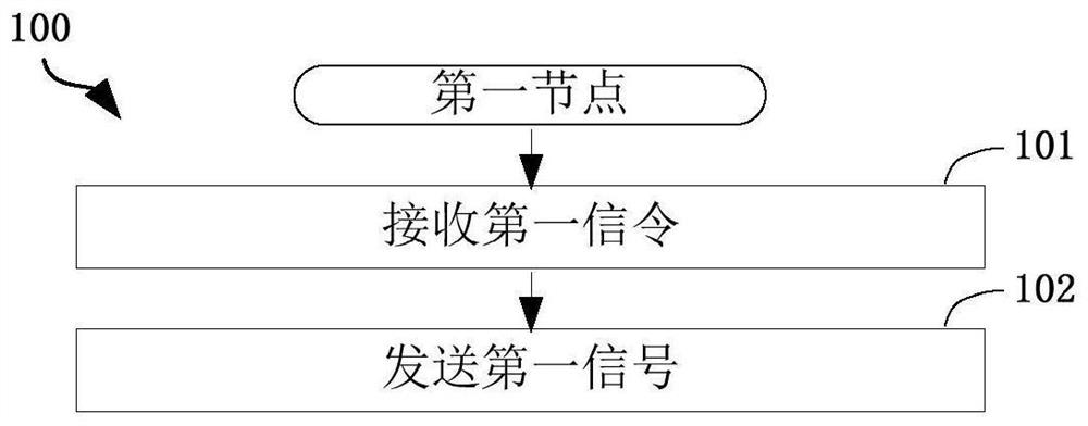
[0076] Embodiment 1 illustrates the flowchart of the first signaling and the first signal according to an embodiment of the present application, as shown in the attached figure 1 shown. in the attached figure 1 In the shown 100, each box represents a step. In particular, the order of the steps in the blocks does not represent a specific chronological relationship between the various steps.

[0077] In Embodiment 1, the first node in this application receives the first signaling in step 101; and sends the first signal in step 102. Wherein, the first signaling includes scheduling information of the first signal; the first signaling includes a first field, and the first field in the first signaling indicates a first information element; the The first information element indicates a first reference signal resource set; the first reference signal resource set includes a positive integer number of reference signal resources; the first reference signal resource set is used to dete...

Embodiment 2

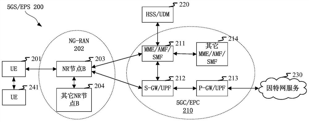
[0169] Embodiment 2 illustrates a schematic diagram of a network architecture according to an embodiment of the present application, as shown in the attached figure 2 shown.

[0170] attached figure 2 The network architecture 200 of LTE (Long-Term Evolution, long-term evolution), LTE-A (Long-Term Evolution Advanced, enhanced long-term evolution) and future 5G systems is described. The network architecture 200 of LTE, LTE-A and future 5G systems is called EPS (Evolved Packet System, Evolved Packet System) 200. The network architecture 200 of 5G NR or LTE can be called 5GS (5G System) / EPS (Evolved Packet System, Evolved Packet System) grouping system) 200 or some other suitable terminology. 5GS / EPS 200 may include one or more UEs (User Equipment, user equipment) 201, a UE241 performing sidelink communication with UE201, NG-RAN (Next Generation Radio Access Network) 202, 5GC (5GCoreNetwork , 5G Core Network) / EPC (Evolved Packet Core, Evolved Packet Core) 210, HSS (Home Subsc...

Embodiment 3

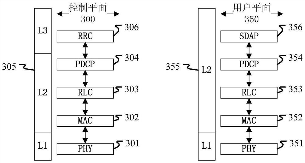
[0182] Embodiment 3 illustrates a schematic diagram of an embodiment of the wireless protocol architecture of the user plane and the control plane according to an embodiment of the present application, as shown in the attached image 3 shown.

[0183] Embodiment 3 shows a schematic diagram of an embodiment of a wireless protocol architecture of a user plane and a control plane according to the present application, as shown in the attached image 3 shown. image 3 is a schematic diagram illustrating an embodiment of a radio protocol architecture for a user plane 350 and a control plane 300, image 3 Use three layers to show the control plane between the first communication node device (UE, gNB or RSU in V2X) and the second communication node device (gNB, UE or RSU in V2X), or between two UEs 300's radio protocol architecture: Layer 1, Layer 2, and Layer 3. Layer 1 (L1 layer) is the lowest layer and implements various PHY (Physical Layer) signal processing functions. The L1 ...


PUM


Abstract

The invention discloses a method and an apparatus in a node used for wireless communication. The method comprises the steps of receiving a first signal by a first node; and sending the first signal. wherein the first signal comprises scheduling information of the first signal; the first signal comprises a first domain, and the first domain in the first signal indicates a first information element; the first information part indicates a first reference signal resource set; the first reference signal resource set comprises a positive integer number of reference signal resources; the first reference signal resource set is used for determining a first parameter group, and the first parameter group is used for sending the first signal; the first parameter set includes which parameters are related to a transmission type of the first signal. According to the method, the uplink and downlink beam management mechanism is unified, the corresponding signal overhead and delay are reduced, and the uplink transmission performance is improved.

Description

technical field [0001] The present application relates to a transmission method and device in a wireless communication system, especially a wireless signal transmission method and device in a wireless communication system supporting a cellular network. Background technique [0002] The multi-antenna technology is a key technology in a 3GPP (3rd Generation Partner Project, third generation partnership project) LTE (Long-term Evolution, long-term evolution) system and an NR (New Radio, new radio) system. Additional spatial degrees of freedom are obtained by configuring multiple antennas at a communication node, such as a base station or a UE (User Equipment, User Equipment). Multiple antennas use beamforming to form beams pointing in a specific direction to improve communication quality. When multiple antennas belong to multiple TRPs (Transmitter Receiver Points, transmitting and receiving nodes) / panels (antenna panels), an additional diversity gain can be obtained by utilizi...

Claims


Application Information

Patent Timeline
Patent Type & Authority Applications(China)
IPC IPC(8): H04L5/00H04W72/12
CPCH04L5/0048H04L5/0053H04W72/20
Inventor 吴克颖张晓博
Owner SHANGHAI LANGBO COMM TECH CO LTD
Why Eureka
Try Eureka