Air conditioner
A technology for air conditioners and compressors, which is applied in air conditioning systems, refrigerators, compressors, etc., to achieve both refrigeration performance and heating performance, increase refrigerant flow rate, and miniaturization
- Summary
- Abstract
- Description
- Claims
- Application Information
AI Technical Summary
Problems solved by technology
Method used
Image
Examples
Embodiment approach 1
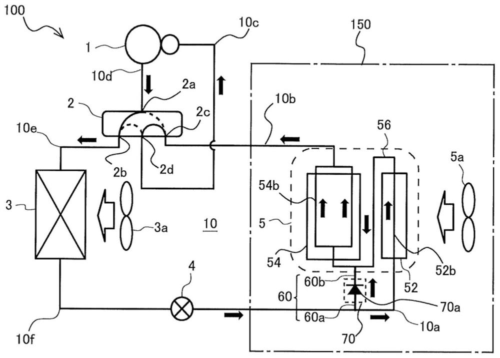
[0020] Air conditioner 100 according to Embodiment 1 of the present invention will be described. figure 1 It is a schematic refrigerant circuit diagram showing an example of the refrigerant circuit 10 during cooling operation of the air conditioner 100 according to the first embodiment. figure 1 The black arrows in indicate the flow direction of the refrigerant during the cooling operation. in addition, figure 1 The hollow frame-shaped arrows in indicate the flow direction of the air flow.
[0021] Additionally, when including figure 1 In the following drawings, the dimensional relationship and shape of each component may be different from the actual situation. In addition, in the following drawings, the same code|symbol is attached|subjected to the same or similar component.
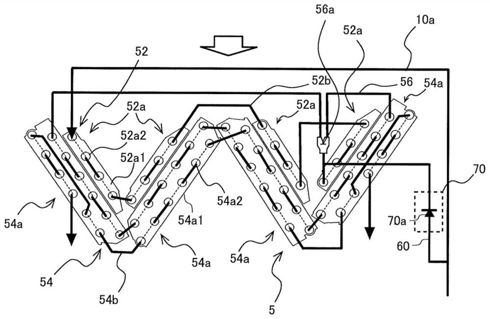
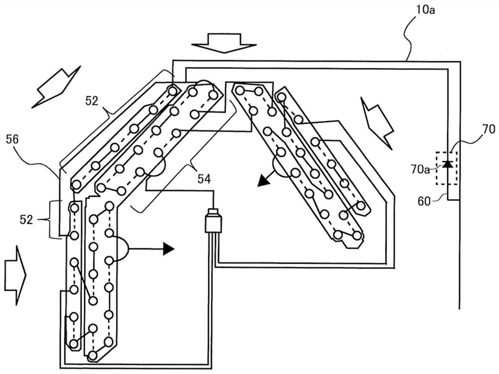
[0022] The air conditioner 100 includes a refrigerant circuit 10 including a compressor 1 , a refrigerant flow switching device 2 , a heat source side heat exchanger 3 , a pressure reducing device 4...
Embodiment approach 2
[0075] use Figure 5 The configuration of the air conditioner 100 according to Embodiment 2 of the present invention will be described. Figure 5 It is a schematic refrigerant circuit diagram showing an example of the refrigerant circuit 10 during cooling operation of the air conditioner 100 according to the second embodiment. Figure 5 The black arrows in indicate the flow direction of the refrigerant during the cooling operation. in addition, Figure 5 The hollow frame-shaped arrows in indicate the flow direction of the air flow.
[0076] Such as Figure 5 As shown, in the air conditioner 100 according to Embodiment 2, the bypass valve 70 is configured to include a capillary 70 b in addition to the check valve 70 a. The rest of the configuration of the air conditioner 100 is the same as that of the first embodiment described above, and therefore description thereof will be omitted.
[0077] The capillary 70b is made of a long and thin copper tube, and is an expansion va...
Embodiment approach 3
[0081] use Figure 6 The configuration of the air conditioner 100 according to Embodiment 3 of the present invention will be described. Figure 6 It is a schematic refrigerant circuit diagram showing an example of the refrigerant circuit 10 in the cooling operation of the air conditioner 100 according to the third embodiment. Figure 6 The black arrows in indicate the flow direction of the refrigerant during the cooling operation. in addition, Figure 6 The hollow frame-shaped arrows in indicate the flow direction of the air flow.
[0082] Such as Figure 6 As shown, in the air conditioner 100 according to Embodiment 3, the bypass valve 70 is configured as a flow rate adjustment valve 70c having a freely adjustable opening degree. Moreover, the air conditioner 100 has the control part 80 which can control the opening degree of the flow rate adjustment valve 70c via the communication line 75. As shown in FIG. In addition, the air conditioner 100 is configured to have one o...
PUM
 Abstract
Description
Claims
Application Information
 - R&D
- Intellectual Property
- Life Sciences
- Materials
- Tech Scout
- Unparalleled Data Quality
- Higher Quality Content
- 60% Fewer Hallucinations
Browse by: Latest US Patents, China's latest patents, Technical Efficacy Thesaurus, Application Domain, Technology Topic, Popular Technical Reports.
© 2025 PatSnap. All rights reserved.Legal|Privacy policy|Modern Slavery Act Transparency Statement|Sitemap|About US| Contact US: help@patsnap.com


