
Cold core manufacturing process and device

A core-making device and cold core technology, applied in the direction of manufacturing tools, cores, metal processing equipment, etc., can solve the problems of sand washing, sand sintering, etc., to improve the strength of sand cores, reduce assembly labor intensity, and improve casting defects Effect

Pending Publication Date: 2021-08-20
WESCAST IND CHINA CO LTD
View PDF6 Cites 0 Cited by
  • Summary
  • Abstract
  • Description
  • Claims
  • Application Information

AI Technical Summary

Problems solved by technology

The patent application decides to use cold core sand or hot core coated sand based on the simplicity or complexity of the specific position of the product structure, without considering the problem that the hot spot of the casting is thick and large, which can easily lead to casting defects such as sand washing and sand sintering

Method used


Image

  • Cold core manufacturing process and device
  • Cold core manufacturing process and device
  • Cold core manufacturing process and device

Examples


Embodiment 1

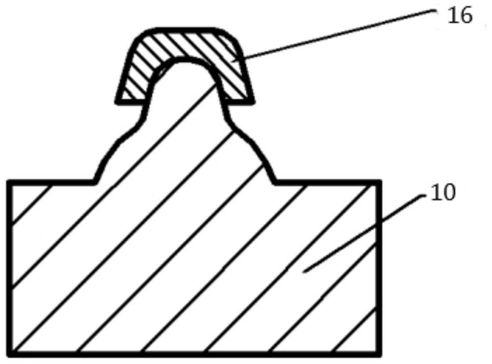
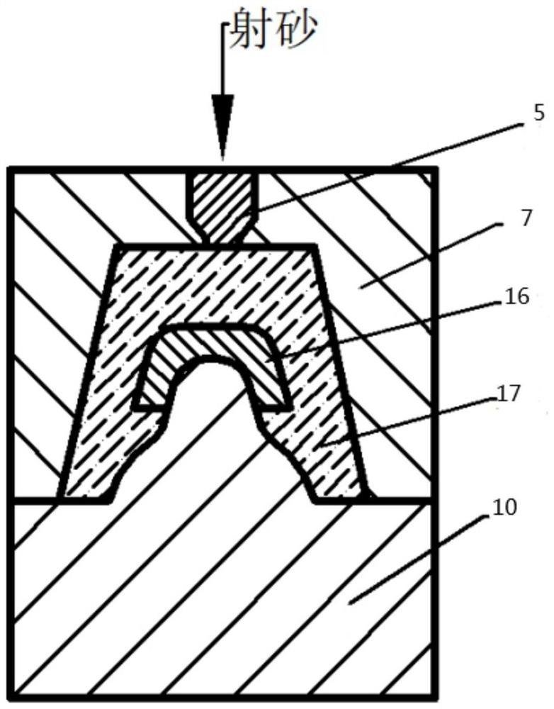
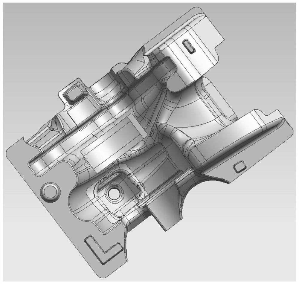
[0035] This embodiment provides a cold core core-making process, which is completed by using a hot core 16 and a cold core box, such as Figure 1-2 shown. A mold cavity is formed in the cold box, and the process includes: inserting a hot core 16 at a designated position of the mold cavity; injecting cold core sand 17 into the mold cavity where the hot core 16 is placed; After the sand 17 wraps the hot core 16, solidify gas is blown into the mold cavity; after the cold core sand 17 solidifies, the sand core is taken out. Sand core products such as image 3 shown. A new cold core making process disclosed by the invention is suitable for improving the quality of casting cold core molds, can effectively improve the quality of sand cores at specific positions, reduce the rate of casting rejects, reduce work intensity, and solve the problems in the current traditional cold core process. Sand core quality problems.

[0036] Described cold core box comprises upper core box 7 and l...

Embodiment 2

[0044] like Figure 4-10 , this embodiment provides a cold core core making device, including an upper mold part and a lower mold part, the upper mold part includes an upper core box 7, an air blowing plate 1, and a sand shooting plate 4, and the air blowing plate 1 And the sand shot plate 4 can move above the upper core box 7; the lower mold part includes a lower core box 10, a lower bottom frame 15, and a lower top plate 13, and the lower core box 10 is placed above the lower bottom frame 15, and the The lower top plate 13 is placed at the bottom of the lower core box 10; when the upper core box 7 and the lower core box 10 are connected together, a cavity is formed, and a designated position is preset in the cavity for placing the thermal core 16 .

[0045] The side of the upper core box 7 facing the lower core box 10 is provided with three guide sleeves 8, wherein one guide sleeve 8 is arranged in the middle of one side, and the other two guide sleeves 8 are arranged at opp...


PUM


Abstract

The invention discloses a cold core manufacturing process and device. A hot core and a cold core box are matched to complete the process, a cavity is formed in the cold core box, and the process comprises the following steps: placing the hot core in a specified position of the cavity; injecting cold core sand into the cavity in which the hot core is placed; after the hot core is wrapped by the cold core sand, blowing curing gas into the cavity; and after the cold core sand is solidified, taking the sand core out. The hot core is adopted to replace an original cold core at the designated position in the cold core box, the hot core prepared in advance is placed at the designated position during core manufacturing, the hot core and the cold core are integrally formed, the strength of the sand core at the specific position can be effectively improved, and the later assembly labor intensity is reduced; and according to the technical scheme, the specific area of the sand core is formed by the hot core, casting defects caused by the sand core can be remarkably improved, in addition, the sand core is rapidly hardened in the cold core box through blowing, and compared with a hot core box, high efficiency and energy saving are better.

Description

technical field [0001] The invention belongs to the field of casting cold box production, and in particular relates to a cold core process for improving the quality of sand cores at a specific position of the cold core, in particular to a cold core core making process and a device. Background technique [0002] As an environmentally friendly product with high efficiency, energy saving and high technology content, turbocharger can improve the exhaust pollution of automobile engine, improve the power and weight ratio of the engine, improve the torque characteristics of the engine, reduce fuel consumption and engine noise, etc. Advantages, it has become the standard configuration of modern automobiles and construction machinery. Turbocharger technology improves the intake air density through the turbocharger, which can comprehensively improve the overall performance of the engine, such as power, economy, and emission indicators, and inject strong power into the engine. It is kn...

Claims


Application Information

Patent Timeline
IPC IPC(8): B22C9/10B22C13/12B22C15/24
CPCB22C9/10B22C13/12B22C15/24
Inventor 姜博
Owner WESCAST IND CHINA CO LTD
Learn More