
Jet channel sand core of diesel engine cylinder head and jet channel casted by using the sand core

A water jet and diesel engine technology, which is used in casting molding equipment, casting molds, cores, etc., can solve the problems of inability to cast parts, unable to adapt to production, waste of manpower and material resources, etc., to improve the strength of the sand core, the structure is simple and reasonable, and the waste is reduced. rate effect

Active Publication Date: 2015-09-09
GUANGXI YUCHAI MASCH CO LTD
View PDF4 Cites 0 Cited by
  • Summary
  • Abstract
  • Description
  • Claims
  • Application Information

AI Technical Summary

Problems solved by technology

2. Manually use raw material tape to cover the copper elbow that is not covered by the core sand, in case the sand core is dipped in paint, there is paint on the copper elbow, and it cannot be melted with the casting after pouring
[0003] In the process of manufacturing sand cores, this production method needs to manually embed and form copper bends, which cannot realize automatic production
After the sand core is made, it still needs a lot of manual processing of the sand core, which wastes a lot of manpower and material resources. This method is very low in production efficiency for making complex bends in the inner cavity of the cylinder head. In the current situation where the level of automation is getting higher and higher However, it is no longer suitable for production, and the production method needs to be improved to meet the requirements of online automatic production.

Method used


Image

  • Jet channel sand core of diesel engine cylinder head and jet channel casted by using the sand core
  • Jet channel sand core of diesel engine cylinder head and jet channel casted by using the sand core

Examples


Embodiment Construction

[0015] A specific embodiment of the present invention will be described in detail below in conjunction with the accompanying drawings, but it should be understood that the protection scope of the present invention is not limited by the specific embodiment. It should be understood that the "upper", "lower", "left", "right", "front" and "reverse" mentioned in the following embodiments of the present invention are all based on the directions shown in the figures, These words used to limit the direction are only for convenience of description, and do not mean to limit the specific technical solution of the present invention.

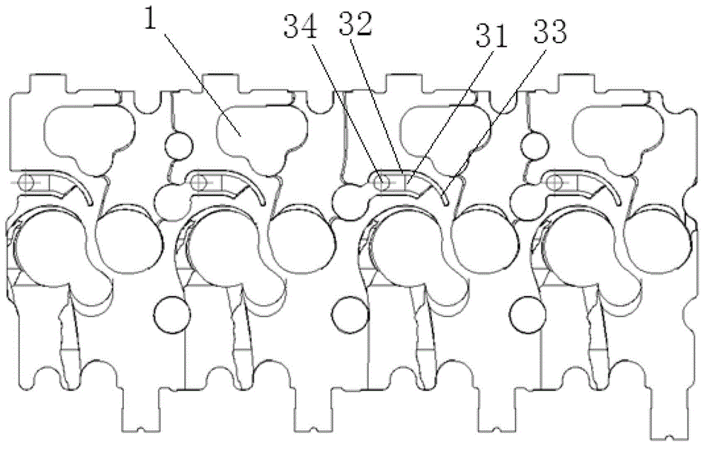
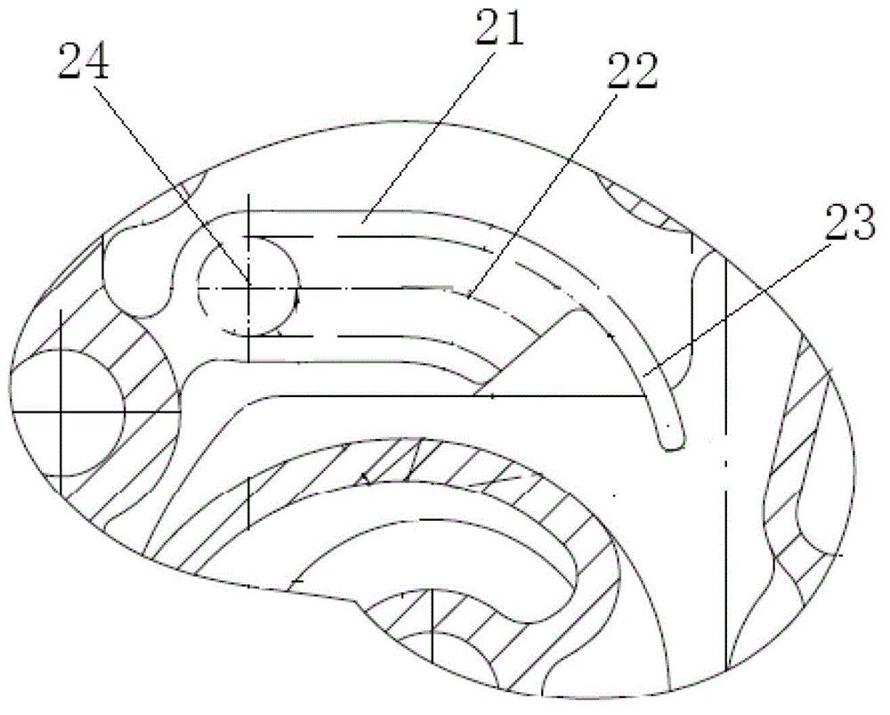
[0016] like figure 1 As shown, the diesel engine cylinder head water jet sand core of the present invention belongs to a part of the cylinder head sand core 1, and is used for casting to form the cylinder head water jet, including: the water jet pipe cavity part sand core 31, the water jet pipe wall part groove 32 And jet baffle type groove 33.

[0017] Wh...


PUM


Abstract

The invention discloses a core of a diesel engine cylinder cover water-ejecting path and a water-ejecting path cast with the core. The core of the diesel engine cylinder cover water-ejecting path belongs to a part of the core of a cylinder cover and is used to cast and form a water-ejecting path of the cylinder cover. The core of the diesel engine cylinder cover water-ejecting path comprises a core of a pipe cavity of the water-ejecting path, a V-shaped groove of the pipe wall portion of the water-ejecting path and a water-ejecting baffle V-shaped groove. The left end of the core of the pipe cavity of the water-ejecting cavity is connected with a core of the inlet portion of the water-ejection path, the V-shaped groove of the pipe wall portion of the water-ejecting path is arranged outside of the side wall of the core of pipe cavity of the water-ejecting path, the water-ejecting baffle V-shaped groove is an arc groove which is bent inwards, and the left end of the water-ejecting baffle V-shaped groove is communicated with the upper wall of the cross section of the right end of the V-shaped groove of the pipe wall portion of the water-ejecting path. The core of the diesel engine cylinder cover water-ejecting path is simple and reasonable in structure. An embedded bending pipe is removed, and a water-ejecting baffle is increased to guide the water-ejecting direction to shorten the water-ejecting path, so that core intensity of the water-ejection path is improved, breaking of the core is prevented, and scrap rate is reduced.

Description

technical field [0001] The invention relates to the field of engines, in particular to a jet channel sand core of a cylinder head of a diesel engine and a jet channel cast with the sand core. Background technique [0002] The cylinder head of a diesel engine is a mechanical part with a complex cavity. Its internal space is compact and there are many complex curved surfaces and irregular channels. In the casting process of the cylinder head, it is necessary to first make a sand core according to the shape of the cavity, and then Put the sand core into the mold, and then close the mold to cast the blank. For general products, if it is necessary to cast a more complicated curved pipe in the inner cavity of the cylinder head (such as the jet channel of the cylinder head of a diesel engine), the formed copper curved pipe is usually pre-embedded in the sand core during the sand core production process. After some special treatment, it can be used to produce castings. This method ...

Claims


Application Information

Patent Timeline
Patent Type & Authority Patents(China)
IPC IPC(8): B22C9/10
Inventor 何春华刘毅张浩陈祖礼龙善北林琳林旭森
Owner GUANGXI YUCHAI MASCH CO LTD
Learn More