
Fairing part and method for forming thin-wall fairing part through selective laser melting

A laser selective melting and fairing technology, applied in additive manufacturing, additive processing, etc., can solve the problems of difficult removal of supports and easy warping deformation of thin-walled structural parts, so as to reduce the cost of additive manufacturing and reduce cracking. risk, guaranteed success

Active Publication Date: 2021-08-20
BEIJING AERONAUTIC SCI & TECH RES INST OF COMAC +1
View PDF11 Cites 6 Cited by
  • Summary
  • Abstract
  • Description
  • Claims
  • Application Information

AI Technical Summary

Problems solved by technology

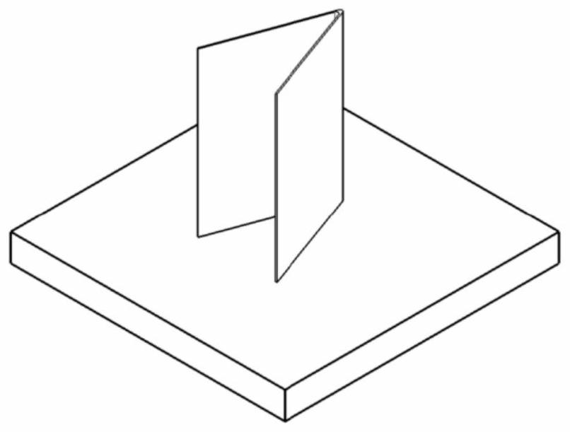
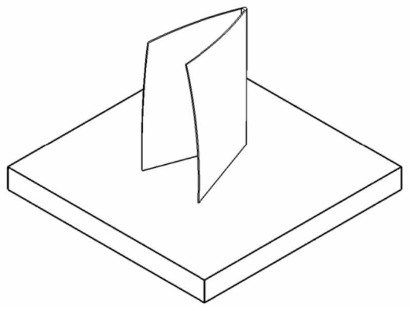
[0006] The object of the present invention is to overcome at least one of the deficiencies of the prior art, and provide a fairing part and a method for forming a thin-walled fairing part by laser selective melting. Formed by laser selective melting technology, this method can not be constrained by the process of traditional manufacturing methods, and the fairing can be manufactured according to the optimal theoretical shape, and the deformation can be controlled through process optimization. The added support structure is easy to remove, which can solve the problem of forming thin-walled structural parts Easy to warp and deform, difficult to remove the support

Method used


Image

  • Fairing part and method for forming thin-wall fairing part through selective laser melting
  • Fairing part and method for forming thin-wall fairing part through selective laser melting
  • Fairing part and method for forming thin-wall fairing part through selective laser melting

Examples


Embodiment Construction

[0037] Specific embodiments of the present invention will be described in detail below in conjunction with specific drawings. It should be noted that the technical features or combinations of technical features described in the following embodiments should not be regarded as isolated, and they can be combined with each other to achieve better technical effects. In the drawings of the following embodiments, the same reference numerals appearing in each drawing represent the same features or components, which can be applied in different embodiments.

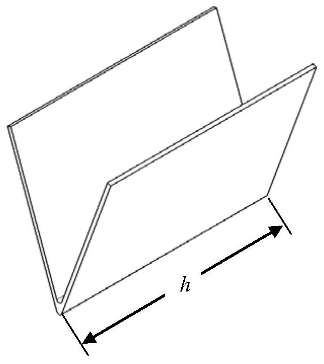
[0038] Without loss of generality, in the following embodiments, multiple titanium alloy V-shaped hanging trailing edge fairings are formed in one printing chamber, and the shape of the fairings is as follows image 3 As shown, the section is V-shaped, such as Figure 4 shown. The titanium alloy V-shaped hanging trailing fairing is a semi-open non-closed thin-walled structure.

[0039] In an embodiment of the present invention, ...


PUM


Abstract

The invention relates to the technical field of preparation of fairing parts, and provides a fairing part and a method for forming a thin-wall fairing part through selective laser melting. The method comprises the steps that data modeling is conducted on the fairing part; a residual stress field and a displacement field of the fairing part are obtained through process simulation, and a supporting structure is added to an area with displacement and stress exceeding certain values; slicing processing is performed to obtain two-dimensional section data information; the two-dimensional section of the part is scanned layer by layer, and selective laser melting forming manufacturing of the fairing part is completed; heat treatment is conducted; and the support is removed and surface treatment is conducted to obtain a finished product. According to the fairing part and the method, the problems that a thin-wall structural part is prone to warping deformation during forming and the support is difficult to remove can be solved; and the additive manufacturing cost can be reduced, the success of the part is ensured, and an effective supporting design method is provided for the thin-wall fairing part.

Description

technical field [0001] The invention relates to the technical field of fairing parts preparation, in particular to a fairing part and a method for forming a thin-walled fairing part by laser selective melting. Background technique [0002] In areas subject to thermal loads such as aircraft suspension and APU, the fairing skin usually adopts heat-resistant metal thin-walled structures such as titanium alloys or high-temperature alloys. The main characteristics of this structure include: thin-walled structure, complex shape, various types, and size The stability and mechanical properties are high, and the dimensional accuracy of the product installation surface and space angle is high. Based on the limitations of traditional manufacturing processes, the fairing components are mainly composed of structural parts such as frames, skins, and ribs. The main sheet metal parts and machined parts of the forming scheme are connected by riveting. This kind of structure is relatively he...

Claims


Application Information

Patent Timeline
Patent Type & Authority Applications(China)
IPC IPC(8): B22F10/28B22F10/85B22F10/38B22F10/64B22F5/00B33Y10/00B33Y40/20B33Y50/02B33Y80/00
CPCB22F3/24B22F5/00B33Y10/00B33Y40/20B33Y50/02B33Y80/00B22F2003/248Y02P10/25
Inventor 彭俊阳王卫东葛增如陈鑫刘建光康梓铭刘倩
Owner BEIJING AERONAUTIC SCI & TECH RES INST OF COMAC
Learn More