
Adjusting assembly based oil injector for mechanical equipment maintenance

A technology for mechanical equipment and adjustment components, applied in mechanical equipment, lubricating oil containers, engine levels, etc., can solve problems such as single function of the oil injector, inability to quantitatively control the amount of oil injected, and inability to realize flexible adjustment of components, etc., to increase the scope of application, Effect of improving oil injection efficiency

Inactive Publication Date: 2021-08-20
郑杰
View PDF0 Cites 2 Cited by
  • Summary
  • Abstract
  • Description
  • Claims
  • Application Information

AI Technical Summary

Problems solved by technology

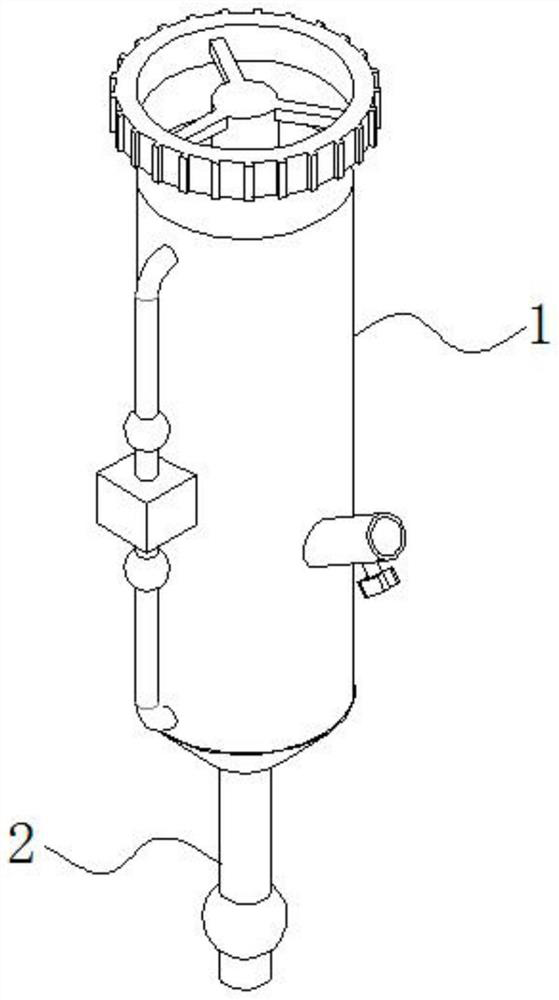
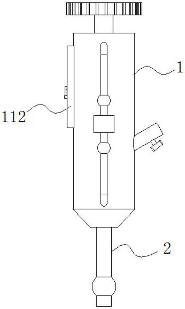
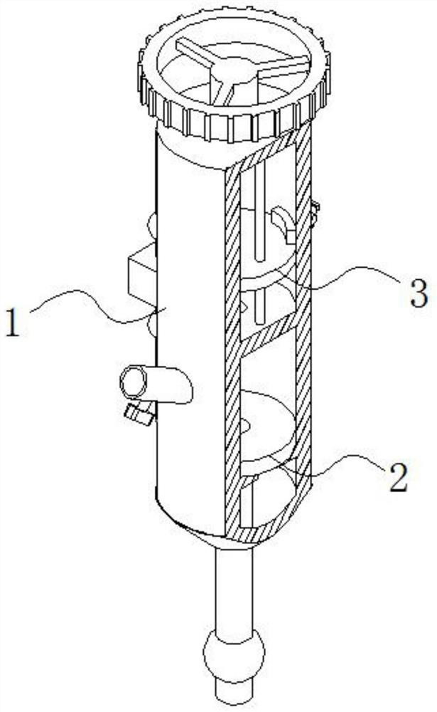
[0004] The object of the present invention is to provide a lubricator for maintenance of mechanical equipment based on an adjustment assembly. The design of the oil chamber, the oil volume control air chamber, the oil outlet assembly and the floating assembly solves the problem that the existing lubricator for maintenance of mechanical equipment has a single function, cannot realize flexible adjustment between corresponding components, and cannot perform quantitative control of the oil injection volume as required , thus greatly reducing the scope of application of the lubricator for mechanical equipment maintenance

Method used


Image

  • Adjusting assembly based oil injector for mechanical equipment maintenance
  • Adjusting assembly based oil injector for mechanical equipment maintenance
  • Adjusting assembly based oil injector for mechanical equipment maintenance

Examples


Embodiment Construction

[0045] The following will clearly and completely describe the technical solutions in the embodiments of the present invention with reference to the accompanying drawings in the embodiments of the present invention. Obviously, the described embodiments are only some of the embodiments of the present invention, not all of them. Based on the embodiments of the present invention, all other embodiments obtained by persons of ordinary skill in the art without creative efforts fall within the protection scope of the present invention.

[0046] see Figure 1-11 , the present invention is an oiler for mechanical equipment maintenance based on an adjustment assembly, including an oil storage mechanism 1;

[0047] The interior of the oil storage mechanism 1 is fixedly connected with a support plate 101; the upper surface of the support plate 101 is provided with a through hole 102;

[0048] An oil outlet assembly 2 and a floating assembly 3 are slidably fitted inside the oil storage mec...


PUM


Abstract

The invention discloses an adjusting assembly based oil injector for mechanical equipment maintenance, and relates to the technical field of machinery. The oil injector comprises an oil storage mechanism; a supporting disc is fixedly connected in the oil storage mechanism; a through hole is formed in the upper surface of the supporting disc; an oil outlet assembly and a floating assembly are arranged in the oil storage mechanism in a sliding fit manner; an oil storage chamber is arranged between the floating assembly and the oil outlet assembly; a driving gas chamber is arranged above the floating assembly; and an oil quantity control gas chamber is arranged below the oil outlet assembly. Through the design of a first gas guide tube, a second gas guide tube, a first electromagnetic valve, a second electromagnetic valve, the oil storage chamber, the driving gas chamber and the oil quantity control gas chamber, the second gas guide tube is utilized to realize pressurization of the oil quantity control gas chamber, and therefore up-down movement of the oil storage chamber is realized, and then movement of a floating disc is flexibly controlled up and down; and the first gas guide tube can be utilized to realize pressurization of the interior of the driving gas chamber, and therefore lubricating oil in the oil storage chamber is pressed out from a lower port of an oil outlet pipe, and the lubricating oil injection efficiency is greatly improved.

Description

technical field [0001] The invention belongs to the technical field of machinery, and in particular relates to an oiler for maintenance of mechanical equipment based on an adjustment assembly. Background technique [0002] Reciprocating power machinery, such as large reciprocating compressors, internal combustion engines, etc., due to the wear and tear of moving parts caused by high-speed and high-frequency operation, will lead to a sharp decline in equipment performance and life. Therefore, in order to improve the friction and wear conditions of moving parts, it is usually necessary to design an independent oil injection lubrication system to perform oil injection and forced lubrication on the friction surface of moving parts. In order to avoid harmful friction between various parts in mechanical equipment and ensure its normal operation, it is necessary to regularly add lubricating oil to the equipment, which is a routine work for mechanical equipment maintenance. [0003...

Claims


Application Information

Patent Timeline
IPC IPC(8): F16N7/30F16N19/00F16N27/02F16N29/00
CPCF16N7/30F16N19/003F16N27/02F16N29/00F16N2250/18F16N2270/72F16N2280/02
Inventor 郑杰
Owner 郑杰
Learn More