Strength testing equipment for mechanical forming material
A technology for strength testing and molding materials, applied in the direction of applying stable tension/pressure to test material strength, analyzing materials, strength characteristics, etc., can solve problems such as accurate strength testing
- Summary
- Abstract
- Description
- Claims
- Application Information
AI Technical Summary
Problems solved by technology
Method used
Image
Examples
Embodiment 1
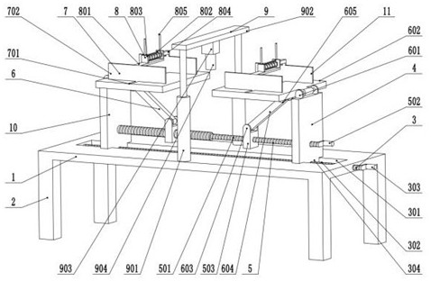
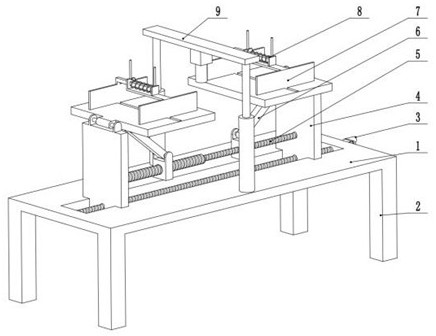
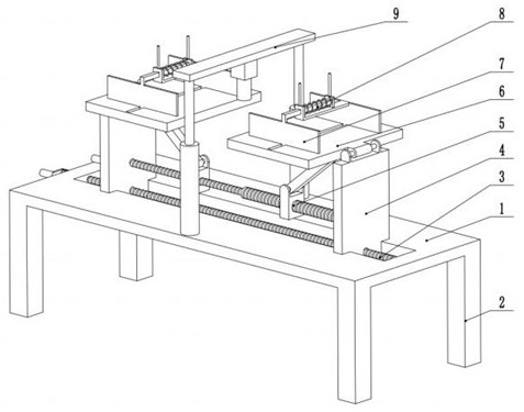
[0030] see Figure 1-7 , a strength testing device for mechanically formed materials, comprising a mounting base 1 and a support leg 2 fixed to the bottom of the mounting base 1;
[0031] The mounting base 1 is provided with a placement plate assembly 10, the placement plate assembly 10 includes a distance adjustment mechanism 3, a mounting plate 4, an adjustment mechanism 5 and a placement plate mechanism 6, the mounting plate 4 is fixed on the distance adjustment mechanism 3, and the adjustment The mechanism 5 is installed on the mounting plate 4, the placing plate mechanism 6 is located on the mounting plate 4 and the adjusting mechanism 5, the distance adjusting mechanism 3 is used to adjust the distance between the mounting plate 4, and the adjusting mechanism 5 is used to adjust the angle of the placing plate mechanism 6, and the placing plate Mechanism 6 is used to place workpieces with different angles;
[0032] A clamping assembly 11 is provided on the placing plate ...
Embodiment 2
[0043] see Figure 7 The other content of this embodiment is the same as that of Embodiment 1, except that the threaded rod mechanism 501 includes a second threaded rod 5011 that is rotatably connected to the mounting plate 4, and a moving hole 5012 is opened in the second threaded rod 5011, and the second The threaded rod 5011 is fixedly connected to the insertion rod 5013 in the moving hole 5012, the second threaded rod 5011 is slidably connected to the third threaded rod 5014, and the end of the third threaded rod 5014 near the insertion rod 5013 is provided with a socket 5015, and the insertion rod 5013 and the first The three threaded rods 5014 are slidingly connected. Specifically, as the distance between the mounting plate 4 changes, the second threaded rod 5011 and the third threaded rod 5014 have a relative displacement at this time, and the second threaded rod 5011 is ensured by the insertion rod 5013 and the socket 5015. And the synchronous rotation of the third thr...
PUM
 Abstract
Description
Claims
Application Information
 - R&D
- Intellectual Property
- Life Sciences
- Materials
- Tech Scout
- Unparalleled Data Quality
- Higher Quality Content
- 60% Fewer Hallucinations
Browse by: Latest US Patents, China's latest patents, Technical Efficacy Thesaurus, Application Domain, Technology Topic, Popular Technical Reports.
© 2025 PatSnap. All rights reserved.Legal|Privacy policy|Modern Slavery Act Transparency Statement|Sitemap|About US| Contact US: help@patsnap.com


