Light emitting module

A light emitting module and incident light technology, applied in the field of integrated optoelectronics and optical communication, can solve the problems of insufficient stability, increased optical loss, and large stress of twisted optical fibers, etc., to reduce optical loss, improve stability, and the process is simple and feasible Effect

Pending Publication Date: 2021-08-20
INST OF SEMICONDUCTORS - CHINESE ACAD OF SCI
View PDF5 Cites 1 Cited by
  • Summary
  • Abstract
  • Description
  • Claims
  • Application Information

AI Technical Summary

Problems solved by technology

The polarization direction can be corrected by adding a twisted fiber, but the twi

Method used


Image

  • Light emitting module
  • Light emitting module
  • Light emitting module

Examples


Embodiment Construction

[0039] In order to make the object, technical solution and advantages of the present invention clearer, the present invention will be described in further detail below in conjunction with specific embodiments and with reference to the accompanying drawings.

[0040] It should be noted that, in the drawings or descriptions of the specification, similar or identical parts all use the same figure numbers. The technical features in the various embodiments exemplified in the specification can be freely combined to form a new solution under the premise of no conflict. In addition, each claim can be used as an embodiment alone or the technical features in each claim can be combined as a new solution. and in the drawings, the shape or thickness of the embodiments may be enlarged, and marked for simplification or convenience. Furthermore, elements or implementations not shown or described in the drawings are forms known to those of ordinary skill in the art. Additionally, while illust...


PUM

PropertyMeasurementUnit
Rotation angleaaaaaaaaaa

Abstract

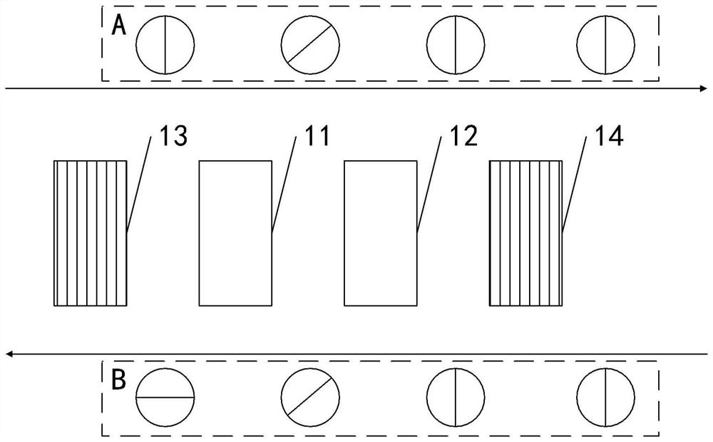
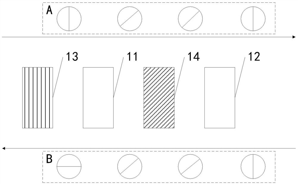
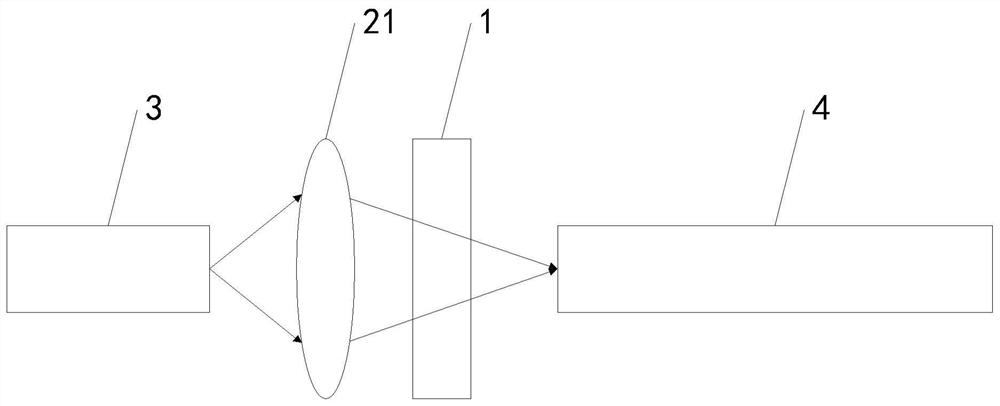
The invention provides a light emitting module comprising an optical isolator (1), the optical isolator (1) comprises a Faraday rotator (11) and a wave plate (12); the Faraday rotator (11) is used for performing non-reciprocal rotation on the polarization direction of an incident light signal, and the wave plate (12) is used for performing reciprocal rotation on the rotated incident light signal to obtain a light signal with the same polarization direction as the incident light signal before rotation; and the wave plate (12) is also used for carrying out reciprocal rotation on the polarization direction of the reflected light signal, and the Faraday rotator (11) is also used for carrying out non-reciprocal rotation on the rotated reflected light signal to obtain an optical signal orthogonal to the polarization direction of the reflected light signal before rotation. According to the light emitting module provided by the invention, the wave plate (12) is introduced into the optical isolator (1), and the optical fiber-free spatial optical coupling scheme of combining the lens with the optical isolator is adopted, so that the optical loss is effectively reduced, and the optical coupling efficiency is improved.

Description

technical field [0001] The invention relates to the technical field of integrated optoelectronics and optical communication, in particular to an optical emission module. Background technique [0002] Integrated optoelectronics is one of the frontiers of development in the field of optical communication, including the monolithic integration of active and passive optoelectronic devices such as various waveguides, polarization rotation, couplers, lasers, detectors and modulators on the same substrate or Hybrid integration of devices on different substrates. [0003] Passive components such as lasers and most modulators are made of different materials and are usually hybrid-integrated. Methods for integrating lasers (InP, InAs) and modulators (Si / Lithium niobate) include: coupling with lenses, via edge coupling / end face coupling, vertical coupling, bonding InP chips or wafers to Si and InP heteroepitaxy Growth on Si et al. Among them, the lens coupling method is the most matu...

Claims


Application Information

Patent Timeline
IPC IPC(8): G02F1/09H04B10/50H04B10/516
CPCG02F1/093H04B10/501H04B10/516
Inventor 王丹丹刘宇李明祝宁华
Owner INST OF SEMICONDUCTORS - CHINESE ACAD OF SCI
Why Eureka
Try Eureka