Method and system for correcting optical proximity effect

A technology of optical proximity effect and correction coefficient, applied in optics, originals for opto-mechanical processing, opto-mechanical equipment, etc., can solve problems such as slow convergence speed, reduce the number of corrections, improve the convergence effect, and speed up the convergence speed. Effect

Active Publication Date: 2021-08-20
南京晶驱集成电路有限公司
View PDF6 Cites 3 Cited by
  • Summary
  • Abstract
  • Description
  • Claims
  • Application Information

AI Technical Summary

Problems solved by technology

This process is repeated until the edge placement error reaches an acceptable value, but the convergence rate is too slow due to the fixed ratio used in the iterative process

Method used


Image

  • Method and system for correcting optical proximity effect
  • Method and system for correcting optical proximity effect
  • Method and system for correcting optical proximity effect

Examples


Embodiment Construction

[0047] The following will clearly and completely describe the technical solutions in the embodiments of the present invention with reference to the accompanying drawings in the embodiments of the present invention. Obviously, the described embodiments are only some, not all, embodiments of the present invention. Based on the embodiments of the present invention, all other embodiments obtained by persons of ordinary skill in the art without creative efforts fall within the protection scope of the present invention.

[0048] Optical proximity correction (optical proximity correction, OPC) is a lithographic enhancement technology, optical proximity correction is mainly used in the production process of semiconductor chips, the purpose is to ensure that the edge of the design pattern is completely etched during the production process. Irregularities in these projected images, such as narrower or wider line widths than designed, can be compensated for by changing the reticle. Other...


PUM


Abstract

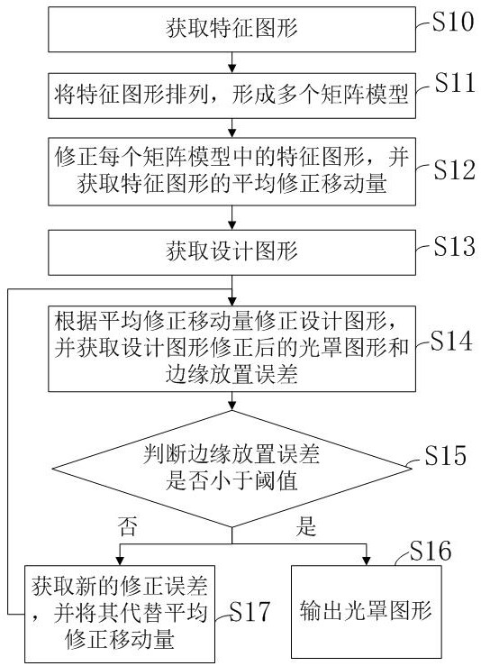
The invention discloses a method and system for correcting anoptical proximity effect. The method comprises the steps: obtaining feature patterns, and arranging the feature patterns to form a plurality of matrix models; correcting the feature graph in each matrix model, and obtaining an average correction movement amount of the feature graph; obtaining a design graph, and correcting the design graph according to the average correction movement amount; obtaining a revised photomask pattern of the design pattern and an edge placement error; judging whether the edge placement error is smaller than a threshold value or not; when the edge placement error is smaller than the threshold value, outputting the photomask pattern; and when the edge placement error is greater than or equal to the threshold value, obtaining a new correction movement amount, and correcting the design graph according to the new positive movement amount. According to the correction method and system for the optical proximity effect, the correction time and the correction frequency can be reduced.

Description

technical field [0001] The invention belongs to the field of integrated circuit manufacturing, in particular to a method and system for correcting optical proximity effects. Background technique [0002] Optical proximity correction (optical proximity correction, OPC) is a lithographic enhancement technology, optical proximity correction is mainly used in the production process of semiconductor chips, the purpose is to ensure that the edge of the design pattern is completely etched during the production process. [0003] Among them, the model-based optical proximity effect correction uses the optical model and the photoresist chemical reaction model to calculate the pattern after exposure. The model-based optical proximity effect correction first needs to identify the edges of the design pattern, so that each edge can move freely , the optical model simulates the pattern of the photoresist after exposure and compares it with the design pattern. The difference between them is...

Claims


Application Information

Patent Timeline
Patent Type & Authority Applications(China)
IPC IPC(8): G03F1/36G03F7/20
CPCG03F1/36G03F7/70441
Inventor 赵广罗招龙李可玉洪银
Owner 南京晶驱集成电路有限公司
Why Eureka
Try Eureka