Retinoscopy optometry device for eye optometry teaching
A technology for retinoscopy and optometry, applied in the field of retinoscopy and optometry, which can solve the problems of damaged lenses, inaccurate placement of lenses, and contamination of lenses in test results, and achieve the effects of automatic replacement, good protection, and high fixation accuracy.
- Summary
- Abstract
- Description
- Claims
- Application Information
AI Technical Summary
Problems solved by technology
Method used
Image
Examples
Embodiment 1
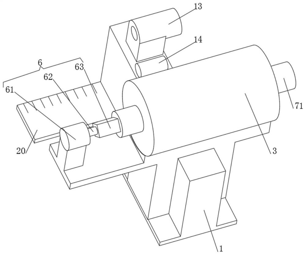
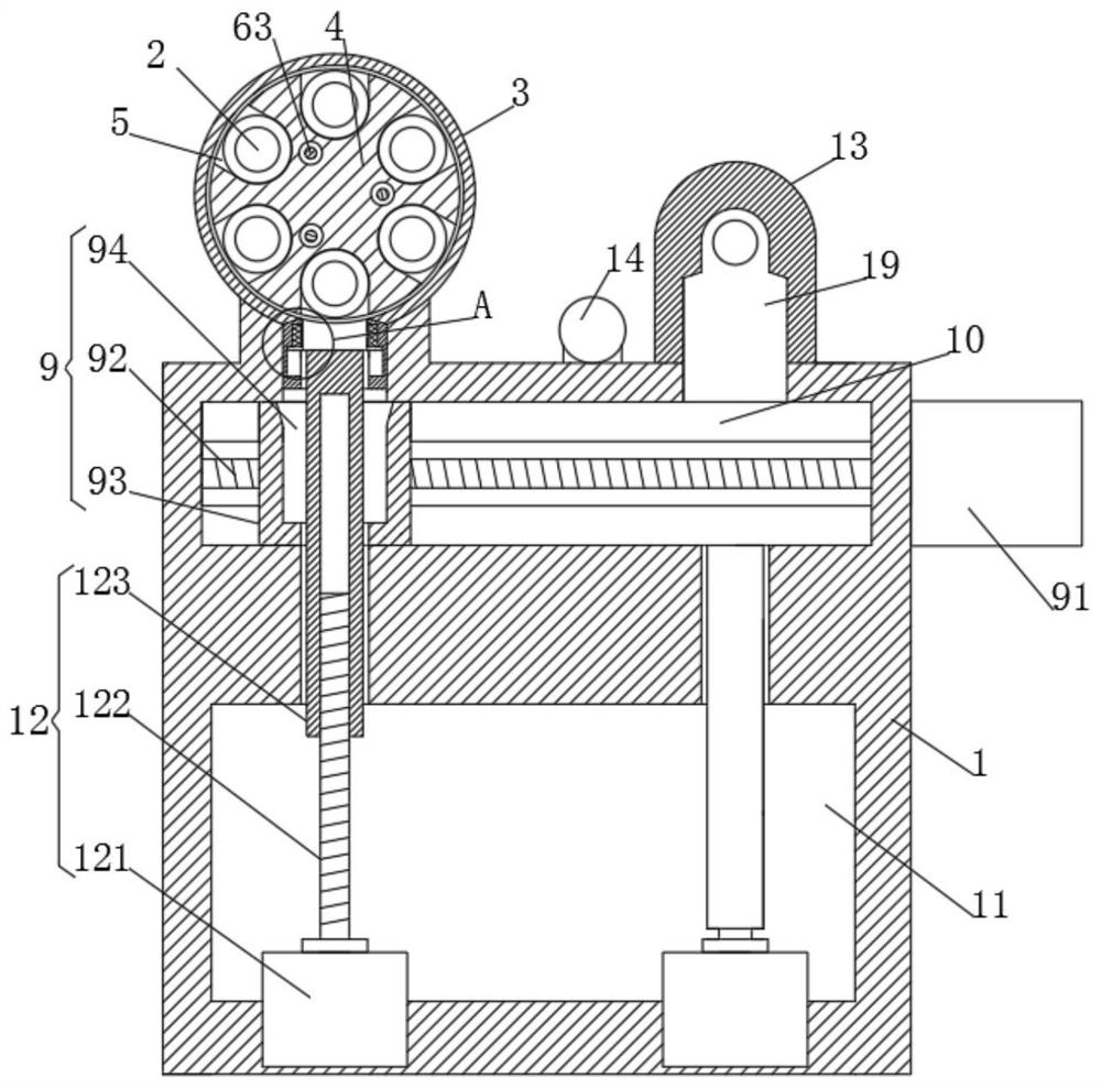
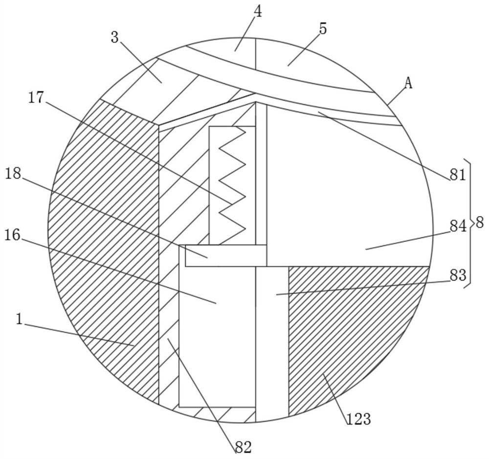
[0039] see Figure 1-5 As shown, the present invention is a retinoscopy device for optometry teaching, including a mounting base 1 and a lens 2, the lens 2 is located above the mounting base 1, and a fixing tube 3 is fixedly installed on the upper side of the mounting base 1 , the inside of the fixed tube 3 is provided with a rotating block 4, the inside of the rotating block 4 is provided with a storage slot 5, the lens 2 is located inside the storage slot 5, one end of the fixed tube 3 is provided with a transmission device 6, and the other end of the fixed tube 3 is provided with a There is a rotating device 7, a slideway 10 is provided on the inside of the mounting base 1, and a film output device 8 is provided at one end of the slideway 10, and a cavity 11 is provided at the inner lower end of the mounting base 1, and a lifting device is provided inside the cavity 11 12. The slideway 10 is provided with a slide device 9, and an inspection tube 13 is fixedly installed on t...
Embodiment 2
[0055] see Figure 1-5 As shown, the present invention is a retinoscopy device for optometry teaching, its use method and working principle are as follows: the first motor 61 transmits the transmission rod 63 through the first screw rod 62, so that the rotating block 4 and The lens 2 in the rotating block 4 moves to the target position, and the structure of the second motor 71, the rotating disc 72, the rotating disc 73 and the rotating shaft 74 drives the rotating block 4 to rotate, so that the rotating block 4 rotates to the target position, so that different degrees The lens 2 can be discharged at the discharge port 81, and the fourth motor 121 in one of them drives the push rod 123 down through the third screw 122. During the downward movement, the device of the slider 82, the chute 83 and the bracket 84 is loaded. The lens 2 moves down and brings the lens 2 into the retaining groove 94 of the transmission block 93. The third motor 91 drives the transmission block 93 to mo...
PUM
 Abstract
Description
Claims
Application Information
 - R&D
- Intellectual Property
- Life Sciences
- Materials
- Tech Scout
- Unparalleled Data Quality
- Higher Quality Content
- 60% Fewer Hallucinations
Browse by: Latest US Patents, China's latest patents, Technical Efficacy Thesaurus, Application Domain, Technology Topic, Popular Technical Reports.
© 2025 PatSnap. All rights reserved.Legal|Privacy policy|Modern Slavery Act Transparency Statement|Sitemap|About US| Contact US: help@patsnap.com


