Thrombus ablation device

A technology of thrombus and plug head, which is applied in the field of medical devices, can solve problems affecting the operation process, cumbersome operation, and inability to adjust, and achieve the effect of shortening the operation process and simple operation

Inactive Publication Date: 2021-08-24
蚌埠冠硕医疗科技有限公司
View PDF1 Cites 0 Cited by
  • Summary
  • Abstract
  • Description
  • Claims
  • Application Information

AI Technical Summary

Problems solved by technology

However, there are still the following problems: (1) The driver, negative pressure suction device, drug injector and other equipment need to be used in sequence during the operation, which is cumbersome and affects the operation process; (2) The size of the embolism cutter used is fixed and cannot be adjusted. It cannot adapt to blood vessels with different diameters. Due to the differences in the diameters of blood vessels in various parts of the human body, it is necessary to replace the equipment when performing operations on different blood vessels.

Method used


Image

  • Thrombus ablation device
  • Thrombus ablation device
  • Thrombus ablation device

Examples


Embodiment 1

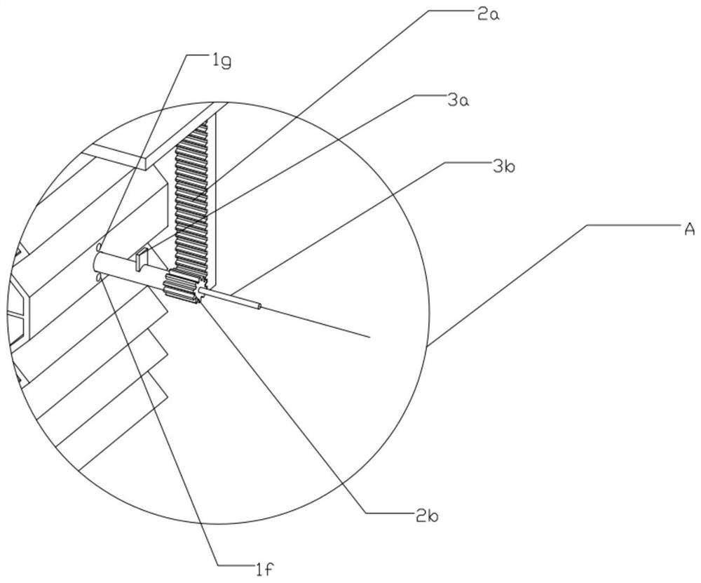
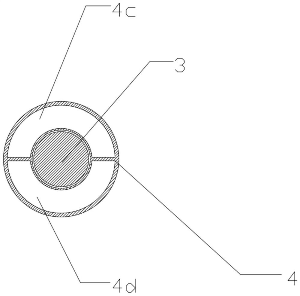
[0030] see Figure 1 to Figure 7 , the present invention provides a technical solution:

[0031] A thrombus ablation device, comprising a pressing box 1, a partition 1c, a transmission straight rod 2a, a transmission gear 2b, a rotating rod 3, an outer tube 4, a nozzle 5, a blade 6, a suction plug 7 and a guide wire 8, and the pressing box A partition 1c is built in the body 1, and the partition 1c divides the pressing box 1 into two parts, the first box 1a and the second box 1b, the pressing box 1 is connected with the outer tube 4, and the outer tube 4 is divided into the second box A tube body 4c and a second tube body 4d are two parts, the first box body 1a communicates with the first tube body 4c, the second box body 1b communicates with the second tube body 4d, and a circle is set in the partition 1c and the outer tube 4 shaped channel, the rotating rod 3 runs through the circular passage of the partition 1c and the outer tube 4, one side of the rotating rod 3 stretches...

Embodiment 2

[0034] see Figure 8 , the present invention provides a technical solution, which is generally the same as Embodiment 1, the difference is that:

[0035]The side of the pressing box 1 is a flexible side 1i, the flexible side 1i can change shape with the change of the volume of the pressing box 1 and has no elasticity. The first box wall 1e of the first box 1a and the second box 1b The second box wall 1h stretches out to press the box body 1, the extension part I1e-1 of the first box wall 1e and the extension part II1e-2 of the second box wall 1h fix the transmission straight rod 2a in the middle, and the transmission straight rod 2a meshes with the transmission gear. A motor is provided on the transmission gear 2b, and the motor can be set to alternately rotate clockwise and counterclockwise at a certain frequency. While the rotating rod 3 drives the blade 6 to rotate, the compression and expansion of the first box body 1a and the second box body 1b can realize thrombolytic dr...

Embodiment 3

[0038] see Figure 9 , the present invention provides a technical solution, substantially the same as Embodiment 2, the difference is:

[0039] A limiting device 1j is installed on the partition 1c, a limiting groove 1k is set on the limiting device 1j, and protrusions corresponding to the limiting groove 1k are set on the first box wall 1e and the second box wall 1h, so that the first The box wall 1e and the second box wall 1h can move stably along the limiting device 1j. Compared with the second embodiment, this embodiment presses the movement of the box body 1 more regularly and stably.

[0040] The above three embodiments of the present invention can realize: 1. The three steps of rotating the blade, injecting thrombolytic drugs, and extracting thrombus fragments are combined through the transmission structure, and the blade can be driven to rotate by pressing the pressing box 1 , or when the motor drives the blade 6 to rotate, pressing the box can complete the steps of i...


PUM


Abstract

The invention provides a thrombus ablation device, and the device comprises a pressing box body, a partition plate, an outer tube, a thrombus suction head and a guide wire; the outer tube is installed on one side of the pressing box body, the guide wire is arranged in the outer tube in a penetrating mode, one end of the guide wire penetrates out of the thrombus suction head, the partition plate is arranged in the pressing box body, and the partition plate divides the pressing box body into a first box body and a second box body. The first box body and the second box body are respectively connected with the outer pipe to form a circulation path, the other end of the outer pipe is provided with an adjustable blade and a thrombus suction head from inside to outside, and the adjustable blade is driven to rotate when the box bodies are pressed to change between an expansion state and a compression state. According to the thrombus removing device, thrombus adhering to the blood vessel wall can be removed, thrombolysis is carried out by spraying the hemolytic suppository on the blood vessel wall, the thrombus adhering to the blood vessel wall can be removed more thoroughly, and hidden dangers caused by residual thrombus on the blood vessel wall are avoided.

Description

technical field [0001] The invention belongs to the field of medical equipment, and in particular relates to a thrombus ablation device. Background technique [0002] At present, thrombus removal devices are widely used in clinical practice. Such devices generally remove thrombus in blood vessels by dissolving, crushing or aspiration, so as to restore blood circulation. However, the existing thrombus removal device is generally provided with a rotating blade inside the suction plug tube, and the thrombus is sucked into the suction plug tube by negative pressure suction, crushed by the rotating blade and pulled out of the body. After peeling off by negative pressure suction, it will still remain on the vessel wall, resulting in incomplete removal of thrombus, which will develop into thrombus and block the vessel again. [0003] Such as prior art patent: Application Publication No. CN111568497A discloses a thrombolysis and thrombolysis removal device and its use method. In th...

Claims


Application Information

Patent Timeline
IPC IPC(8): A61B17/22A61B17/3203A61B17/3207
CPCA61B17/22A61B17/32037A61B17/320758A61B2017/22038A61B2017/22079A61B2017/22082A61B2017/22084A61B2017/320741A61B2017/320775
Inventor 汤文凯
Owner 蚌埠冠硕医疗科技有限公司
Why Eureka
Try Eureka