Production equipment for drawing copper pipe

A technology for producing equipment and copper tubes, which is applied to wire drawing dies, mandrels, etc., can solve problems such as low production efficiency, and achieve the effects of good discharge, convenient feeding, and avoidance of scratches.

Pending Publication Date: 2021-08-24
CHONGQING LONGYU PRECISION COPPER TUBE CO LTD
View PDF0 Cites 1 Cited by
  • Summary
  • Abstract
  • Description
  • Claims
  • Application Information

AI Technical Summary

Problems solved by technology

[0005] The present invention intends to provide a production equipment for drawing copper pipes to solve the problem of low production efficiency in the existing drawing method

Method used


Image

  • Production equipment for drawing copper pipe
  • Production equipment for drawing copper pipe
  • Production equipment for drawing copper pipe

Examples


Embodiment 1

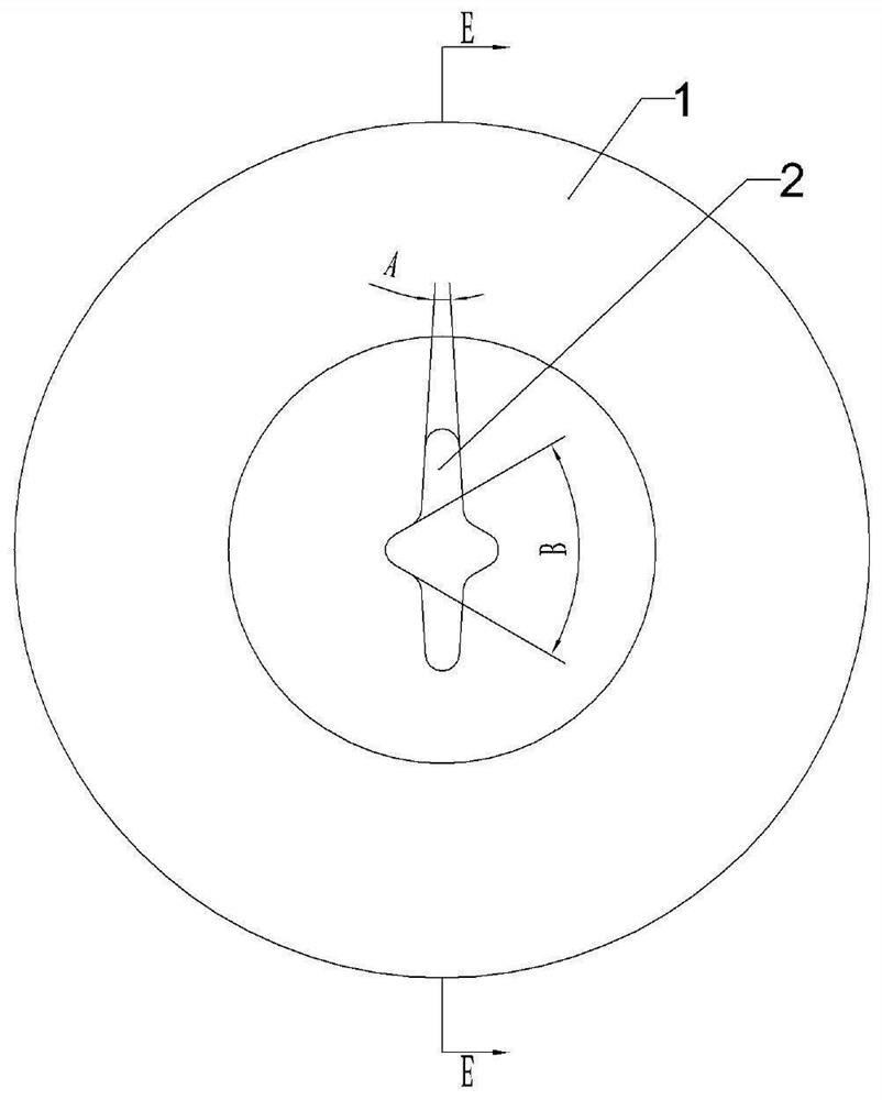
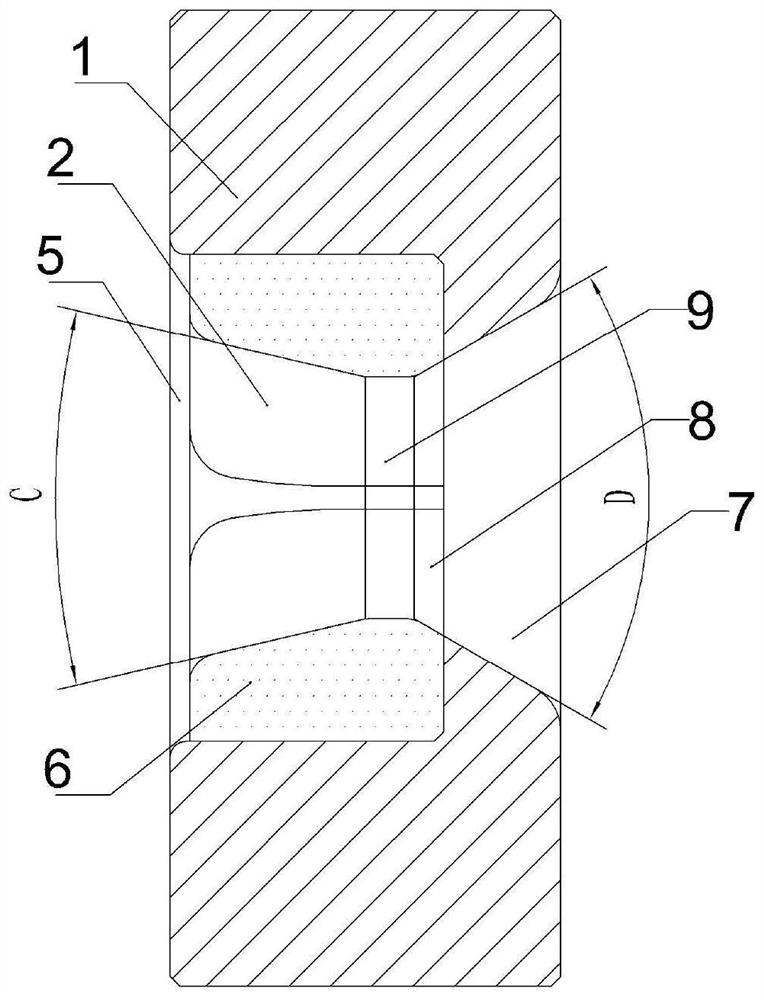
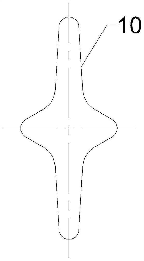
[0039] A kind of production equipment for stretched copper pipes, including an inner oiling mechanism, a straightening mechanism, a preforming mechanism, a drawing die and a cutting mechanism, the inner oiling mechanism is used for oiling the inside of the copper pipe, and the straightening mechanism is used for Copper coil tube straightening, pre-forming mechanism is used to extrude and pre-form the straightened copper tube into an oval shape, the drawing die is used to draw the pre-formed copper tube into a cross-shaped tube, and the cutting mechanism is used to Cut the drawn pipe. In this embodiment, the inner oiling mechanism adopts the oiler for oiling the inside of the copper pipe in the prior art, the straightening mechanism adopts the double-roller straightening mechanism used in the drawing of the copper pipe in the prior art, and the preforming mechanism also Extrusion dies in the prior art are used, and the cutting mechanism is the pipe cutting machine in the prior ...

Embodiment 2

[0051] The difference between this embodiment and the first embodiment lies in that the structure of the external oiling mechanism is different. Specifically, such as Figure 6 As shown, the outer oiling mechanism includes a sleeve 15, and the sleeve 15 is axially penetrated with a passage 14 for copper pipes to pass through. The right end of the sleeve 15 can be installed on the left end of the outer mold through bolts. After installation, the passage 14 and the outer mold through-hole connection.

[0052] On the channel 14 inwalls, an oiling sleeve 22 is installed in rotation, combined with Figure 7 It can be seen that the oil-coated sleeve 22 includes a mesh-like skeleton 23, and the skeleton 23 is filled with an oil-absorbing layer 24. In this embodiment, the oil-absorbing layer 24 adopts oil-absorbing cotton, and the inner wall of the oil-coated sleeve 22 is glued and fixed with an oil-coated layer 25. The oil-coated layer 25 adopts soft and oil-absorbing materials suc...

Embodiment 3

[0059] Such as Figure 8 As shown, the difference between the present embodiment and the second embodiment is that there is an annular piston chamber 28 inside the sleeve 15, the piston chamber 28 is located on the left side of the oil storage chamber 16, and the piston chamber 28 and the sleeve 15 are arranged concentrically. An annular piston 27 is slidably installed in the piston chamber 28, and the piston 27 is connected with a cylinder. The left end of the piston cavity 28 is uniformly connected with several blowing pipes 26 , and the blowing pipes 26 are obliquely aligned with the entrance of the channel 14 . The right end of the piston chamber 28 is uniformly connected with some air suction pipes 30, the air suction pipe 30 is installed on the inside of the piston chamber 28, the free end of the air suction pipe 30 faces the passage 14, and the air suction pipe 30 is equipped with a unidirectional air inlet towards the piston chamber 28. one-way valve. The outside of ...


PUM

PropertyMeasurementUnit
lengthaaaaaaaaaa
lengthaaaaaaaaaa
radiusaaaaaaaaaa

Abstract

The invention relates to the technical field of copper pipe drawing, in particular to production equipment for drawing a copper pipe. The production equipment comprises an inner oil coating mechanism, a straightening mechanism, a pre-forming mechanism, a drawing die and a cutting mechanism; the drawing die comprises an outer die and a moving core head, the outer die comprises a die sleeve and a die core, a through hole is axially formed in the die sleeve, the die core is embedded in the through hole, a conical core hole is formed in the die core, the core hole is communicated with the through hole, the cross section of the core hole is cross-shaped, and the core hole is used for being matched with the moving core head; and the moving core head comprises a large-diameter section, a small-diameter section and a transition section, the transition section is smoothly connected between the large-diameter section and the small-diameter section, and the shape of the cross section of the moving core head is the same as that of the cross section of the core hole. The production equipment can solve the problem that an existing drawing manner is low in production efficiency.

Description

technical field [0001] The invention relates to the technical field of copper pipe drawing, in particular to production equipment for drawing copper pipes. Background technique [0002] At present, gas water heaters are equipped with double-eared, cross-shaped and other special-shaped copper tubes to replace ordinary cylindrical copper tubes to improve heat exchange efficiency and speed up the time for hot water to flow out. Special-shaped copper tubes such as double-eared and cross-shaped copper tubes are generally drawn from cylindrical copper tube blanks. [0003] The special-shaped copper tube drawing die generally includes an outer mold and a core head. In the prior art, the core head generally adopts a fixed core head, inserts a core rod into the core head, and fixes the core head to the core hole of the outer mold through the core rod. The copper tube blank is sleeved outside the core head, passed through the core hole and connected with the stretching machine. When...

Claims


Application Information

Patent Timeline
Patent Type & Authority Applications(China)
IPC IPC(8): B21C3/02B21C3/16B21C9/00B21C37/06
CPCB21C3/02B21C3/16B21C9/00B21C37/06
Inventor 娄助军张德志刘俊彪张旭辉李玉林
Owner CHONGQING LONGYU PRECISION COPPER TUBE CO LTD
Why Eureka
Try Eureka