
Machining machine and machining process for manufacturing steel pipe structure of steel pipe truss

A steel pipe truss and processing machinery technology, applied in the field of steel pipe truss production, can solve the problems of increased cost, time-consuming and laborious, single function, etc., and achieve the effect of easy installation and removal

Active Publication Date: 2021-08-24
QINGDAO ZHANGSHI MACHINERY
View PDF6 Cites 1 Cited by
  • Summary
  • Abstract
  • Description
  • Claims
  • Application Information

AI Technical Summary

Problems solved by technology

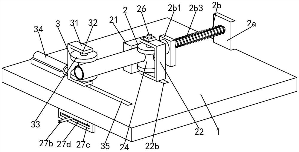
[0005] The invention provides a steel pipe truss manufacturing steel pipe structure processing machinery and processing technology, which can solve the following problems in the steel pipe truss manufacturing steel pipe structure processing process: a. At present, the traditional steel pipe can only be bent for a certain type Dimensions, it is impossible to bend steel pipes of various sizes and specifications. At the same time, when traditional bending equipment bends steel pipes, it cannot process steel pipes with different angles, only one bending angle can be realized, and the function is single. , the effect is limited; b. When the existing bending equipment is bent, there is a concave deformation at the bending part of the steel pipe, which often needs to be repaired, which is time-consuming and laborious, and some steel pipes are even scrapped directly, which increases the cost. A certain springback, resulting in the bending angle of the final formed steel pipe does not meet the requirements, and needs to be processed again

Method used


Image

  • Machining machine and machining process for manufacturing steel pipe structure of steel pipe truss
  • Machining machine and machining process for manufacturing steel pipe structure of steel pipe truss
  • Machining machine and machining process for manufacturing steel pipe structure of steel pipe truss

Examples


Embodiment Construction

[0034] Embodiments of the present invention will be described below with reference to the drawings. In the process, in order to ensure the clarity and convenience of illustration, we may exaggerate the width of the lines or the size of the constituent elements in the diagram.

[0035] In addition, the following terms are defined based on the functions in the present invention, and may be different according to the user's or operator's intention or practice. Therefore, these terms are defined based on the entire content of this specification.

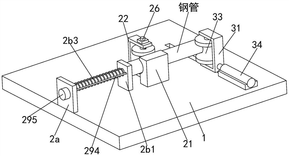
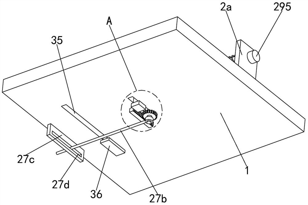
[0036] Such as Figure 1 to Figure 9 As shown, a steel pipe truss manufacturing steel pipe structure processing machine, including a workbench 1, a support limit device 2 and a bending device 3, the workbench 1 is provided with a support limit device 2 and a bending device 3, the The bending device 3 is located on the left side of the support limit device 2; wherein:

[0037] The support limit device 2 includes a fixed block 21, a mount...


PUM


Abstract

The invention provides a machining machine and a machining process for manufacturing a steel pipe structure of a steel pipe truss. The machining machine comprises a workbench, a supporting and limiting device and a bending device. According to the device, the following problems existing in the machining process of manufacturing the steel pipe structure of the steel pipe truss can be solved of a, bending machining can only be carried out for a certain size when traditional steel pipes are bent at present, bending machining cannot be carried out on the steel pipes of various sizes, meanwhile when traditional bending equipment is used for bending the steel pipes, steel pipes with different angles cannot be machined, only one bending angle can be achieved, the function is single, and the effect is limited; and b, when the existing bending equipment is used for bending, the bending part of the steel pipe is sunken and deformed, repairing is often needed, time and labor are wasted, even some steel pipes are directly scrapped, the cost is increased, meanwhile, certain resilience exists after the steel pipe is bent, so that the bending angle of the finally formed steel pipe does not meet the requirement, and the steel pipe needs to be processed again.

Description

technical field [0001] The invention relates to the technical field of steel pipe truss production, in particular to a steel pipe truss production steel pipe structure processing machine and processing technology. Background technique [0002] A truss is a structure made up of members connected to each other by hinges at both ends. The truss is composed of straight rods and generally has a plane or space structure of triangular units. The truss members mainly bear axial tension or pressure, so that the strength of the material can be fully utilized. When the span is large, it can save materials compared with solid web beams, reduce self-weight and Increase stiffness. The advantage of the truss is that the rods mainly bear tension or pressure, which can give full play to the role of materials, save materials, and reduce structural weight. Commonly used are steel truss, reinforced concrete truss, prestressed concrete truss, wooden truss, steel and wood composite truss, steel...

Claims


Application Information

Patent Timeline
IPC IPC(8): B21D7/024B21D43/00B21D7/12
CPCB21D7/024B21D43/003B21D7/12
Inventor 任菊华
Owner QINGDAO ZHANGSHI MACHINERY
Learn More