
A Vibration Fatigue Test Device for Fan Blades with Protruding Shoulder of Engine

A technology of vibration fatigue and test equipment, which is applied in vibration testing, measuring equipment, testing of machine/structural components, etc. It can solve the problems of destroying the blade structure and the inability to accurately simulate the boundary conditions of the blade, etc., and achieves a wide range of applications and is easy to fatigue The effect of testing and facilitating the adjustment of preload force

Active Publication Date: 2021-11-30
AECC AVIATION POWER CO LTD
View PDF14 Cites 0 Cited by
  • Summary
  • Abstract
  • Description
  • Claims
  • Application Information

AI Technical Summary

Problems solved by technology

In order to shorten the test period, the traditional test method cuts off the boss of the blade, which not only destroys the structure of the blade itself, but also cannot accurately simulate the boundary conditions of the blade. At present, there is no test method and device

Method used


Image

  • A Vibration Fatigue Test Device for Fan Blades with Protruding Shoulder of Engine

Examples


Embodiment Construction

[0026] The present invention is described in further detail below in conjunction with accompanying drawing:

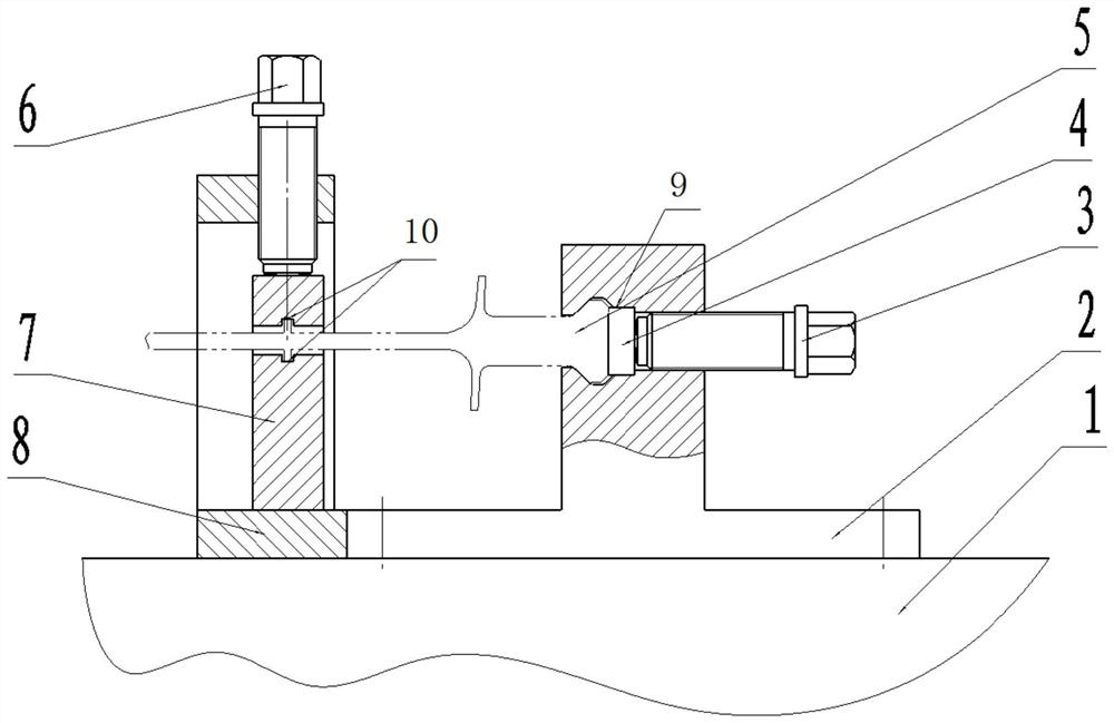
[0027] Such as figure 1 As shown, a vibration fatigue test device for fan blades with shoulders of an engine includes a tenon positioning block 2, a shoulder clamping block 7 and a shoulder fixing frame 8, and the tenon positioning block 2 and shoulder fixing frame 8 are fixed on a vibration table 1 superior;

[0028] The tenon positioning block 2 is provided with a tenon ejector groove and a tenon groove 9, and the tenon ejector groove is provided with a tenon ejector 3, and the tenon ejector groove communicates with the tenon groove 9, and the section of the tenon groove 9 coincides with the blade tenon 5;

[0029] The shoulder clamping block 7 is provided with a shoulder groove 10 for supporting the blade shoulder. The shoulder groove 10 is a through-hole structure along the axial direction of the blade shoulder, and the shoulder groove 10 is an open structure alon...


PUM


Abstract

The invention discloses a vibration fatigue test device for fan blades with shoulders of an engine. The positioning and tightening of the tenons of the blades is realized by using a tenon push rod, and a shoulder groove for supporting the shoulders of the blades is provided on the shoulder clamping block. Realize the positioning and holding of the blade shoulder, and then use the shoulder pin on the shoulder fixing frame to realize the clamping of the blade shoulder to ensure the suspension of the shoulder structure on the fan blade with shoulder of the engine; then put the tenon positioning block and the shoulder The fixed frame is fixed on the vibration table, and the vibration fatigue test of the fan blade with shoulder is completed by using the vibration table. This device can accurately simulate the working state of the blade, and complete the high cycle fatigue assessment test of the blade to ensure reliable fatigue test data. , the device has a simple and compact structure, is easy to adjust, and can flexibly adjust the position according to the needs of the test blade; at the same time, it can be widely used in other types of blades, with a wide range of applications, strong applicability, and strong engineering application value.

Description

technical field [0001] The invention belongs to the technical field of engine blade tests, in particular to a vibration fatigue test device for engine blades with shoulders. Background technique [0002] The high cycle fatigue damage of blades caused by vibration is a key problem restricting the reliability of engines. Researching the causes of blade vibration and reducing blade vibration damage has always been a matter of great concern in engine design and production. The new engine uses shoulder blades to solve the vibration problem. The shoulder blades increase the stiffness of the blade due to the addition of auxiliary supports on the blade body. , change the natural frequency and mode shape of the blade without shoulder, reduce the vibration response of the blade, and minimize the vibration stress of the blade during work. Therefore, how to accurately simulate the vibration state of the blade and carry out the vibration fatigue test on this basis is a difficult problem...

Claims


Application Information

Patent Timeline
Patent Type & Authority Patents(China)
IPC IPC(8): G01M7/02
CPCG01M7/027
Inventor 蔡婉花田齐闫志祥吴生让赵飞李鹏
Owner AECC AVIATION POWER CO LTD
Learn More