Gearless coupler and multi-angle screwdriver

A technology without gears and couplings, applied in screwdrivers, couplings, elastic couplings, etc., can solve the problems of high manufacturing cost, not enough economy, not enough convenience, etc., to improve the appearance, reduce the difficulty of work, rotate Effort-saving effect

Active Publication Date: 2021-08-24
中铁建工集团建筑安装有限公司 +1
View PDF7 Cites 1 Cited by
  • Summary
  • Abstract
  • Description
  • Claims
  • Application Information

AI Technical Summary

Problems solved by technology

This invention can solve the problem of difficult fastening screws in some narrow spaces, but the structure of the traditional universal cross joint coupling is complicated, and the manufacturing cost is high. It is difficult to fully function in a small space, and it is not convenient enough; its complicated structure makes it difficult to repair the universal screwdriver through simple repairs after it is damaged, which is not economical

Method used


Image

  • Gearless coupler and multi-angle screwdriver
  • Gearless coupler and multi-angle screwdriver
  • Gearless coupler and multi-angle screwdriver

Examples


Embodiment 1

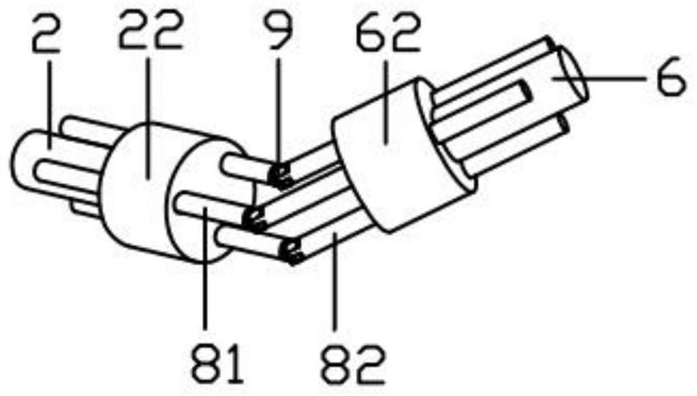
[0053] image 3 Shown is a gearless coupling in this embodiment, including a first rotor 2, a second rotor 6 and three connecting rods 8; the end of the first rotor 2 is sleeved with a first turntable 22; the The end of the second rotor 6 is sleeved with the second turntable 62; the connecting rod 8 includes a driving rod 81 and a driven rod 82; there is an angle between the driving rod 81 and the end of the driven rod 82; 81 penetrates the outer edge of the first turntable 22 and slides with the first turntable 22; the driven rod 82 penetrates the outer edge of the second turntable 62 and slides with the second turntable 62; The distance between the axis of a turntable 22 is equal to the distance between the axis of the driven lever 82 and the second turntable 62, and the direction in which the active lever 81 rotates with the first turntable 22 is driven by the driven lever 82. The rotation direction of the second turntable 62 is the same, and both rotate clockwise or count...

Embodiment 3

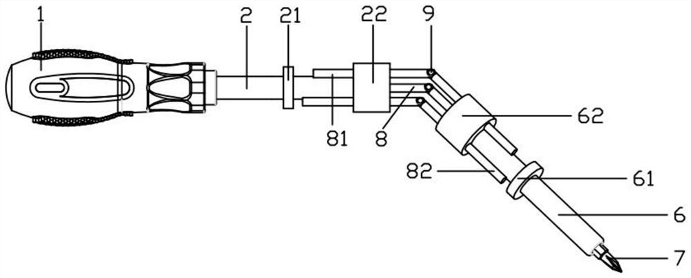
[0079] A method of using a multi-angle screwdriver, the specific steps are as follows: adjust the angle between the active rod 81 and the driven rod 82, make the movable cutter head 7 close to the screw and match it, and stabilize the distance between the first turntable 22 and the second turntable 62 Rotate the handle 1 to drive the first rotor 2 and the first turntable 22 at its end to rotate, the first turntable 2 drives the driving rod 81 and the driven rod 82 to rotate, and transmits the torque to the second turntable 62, so that The second rotating disk 62 and the second rotor 6 coaxially affixed with the second rotating disk 62, the movable cutter head 7 coaxially affixed with the second rotor 6, and the screw that coincides with the movable cutter head 7 rotate to make the screw tighten or loose.

Embodiment 4

[0081] The using method of the present invention is as follows:

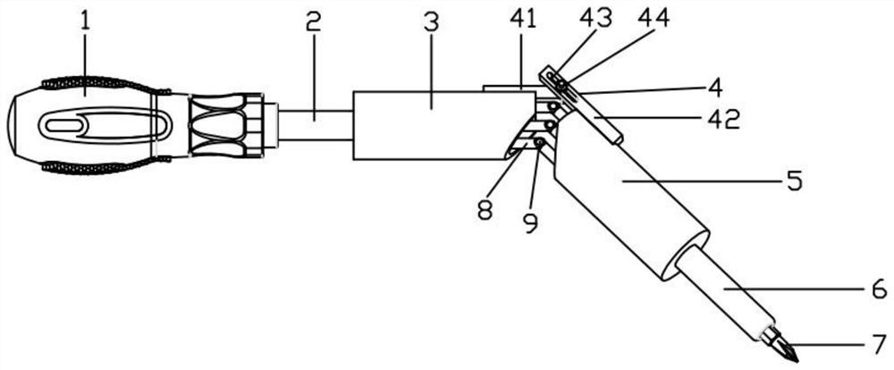
[0082] A method of using a multi-angle screwdriver, the specific steps are as follows: turn the handle 1 to drive the movable cutter head 7 to rotate to tighten the bolt; adjust the sleeve adjustment part 4 to make the handle 1 and the movable cutter head 7 at a suitable angle, and then tighten the nut 44 for fixing; turning the handle 1 drives the first rotor 2 to rotate, the first rotor 2 drives the first turntable 22 to rotate, the first turntable 22 drives the connecting rod 8 to rotate, and the link 8 drives the second turntable 62 Rotate, the second turntable 62 drives the second rotor 6 to rotate, and the second rotor 6 drives the movable cutter head to rotate; finally tighten the screw.


PUM


Abstract

The invention discloses a gearless coupler and a multi-angle screwdriver. The gearless coupler comprises a first rotor, a second rotor and at least one connecting rod. The end part of the first rotor is fixedly connected with a first rotary disc. The end part of the second rotor is fixedly connected with a second rotary disc. The connecting rod comprises a driving rod and a driven rod. The end parts of the driving rod and the driven rod are not collinear when being connected. The driving rod penetrates into the part, deviating from the axis, of the first rotary disc and is in sliding fit with the first rotary disc. The driven rod penetrates into the part, deviating from the axis, of the second rotary disc and is in sliding fit with the second rotary disc. The multi-angle screwdriver comprises a handle and a movable tool bit connected with the handle, the gearless coupler is connected between the handle and the movable tool bit, and the handle is fixedly connected with the first rotor; and the movable tool bit is coaxially and fixedly connected with the second rotor. By means of the gearless coupler and the multi-angle screwdriver, the angle can be changed to transmit torque, and the screwdriver can fasten a screw in a narrow space.

Description

technical field [0001] The invention relates to the field of couplings, in particular to a gearless coupling. [0002] The invention also relates to a multi-angle screwdriver. Background technique [0003] Most of the existing universal joints are cross-shaft universal joints and ball-cage universal joints, but the universal joints have complex structures, high manufacturing costs and damage after damage. Problems that are hard to fix. [0004] At present, most of the equipment needs to use screws when installing the screws. When tightening the screws, there is often a problem of narrow operating space. As a result, ordinary screwdrivers will interfere with other equipment or mounting frames, making it impossible to fasten the screws quickly and reliably. This situation greatly increases the work difficulty of the worker, reduces work efficiency, and there may be potential safety hazards when the screw is not fastened completely. [0005] Chinese invention patent publicat...

Claims


Application Information

Patent Timeline
Patent Type & Authority Applications(China)
IPC IPC(8): F16D3/06F16D3/08F16D3/84F16D41/12B25B15/00B25B23/00
CPCF16D3/06F16D3/08F16D3/84F16D41/12B25B15/00B25B23/00
Inventor 李灿灿张志斌滕广武焉志远杨洪涛李珍赵建伟李青松
Owner 中铁建工集团建筑安装有限公司
Why Eureka
Try Eureka