Metallographic preparation device for material science and engineering

A material science and preparation device technology, applied in the field of material science and engineering, can solve the problems of operator fatigue, troublesome operation, inconvenient metallographic sample production, etc., to reduce friction and facilitate grinding and use.

Pending Publication Date: 2021-08-24
HOHAI UNIV
View PDF10 Cites 0 Cited by
  • Summary
  • Abstract
  • Description
  • Claims
  • Application Information

AI Technical Summary

Problems solved by technology

[0003] In the current existing technology, in the process of metallographic sample preparation, the grinding and polishing of metallographic samples is mostly performed manually, which is cumbersome to operate, and long-term work also leads to operator fatigue, which affects the metallographic test. At the same time, in the existing polishing process, it is necessary to repeatedly lubricate and clean the polished metallographic sample. When lubricating, it needs to be removed for sample, which is troublesome, cumbersome to operate, and inconvenient for metallographic sample production; When the metallographic sample is polished, it is necessary to remove the sample to confirm the polishing degree of the metallographic sample surface. Repeated confirmation, the operation is cumbersome, time-consuming and laborious, which affects the production efficiency of the metallographic sample and is not conducive to the production of the metallographic sample.

Method used


Image

  • Metallographic preparation device for material science and engineering
  • Metallographic preparation device for material science and engineering
  • Metallographic preparation device for material science and engineering

Examples


Embodiment

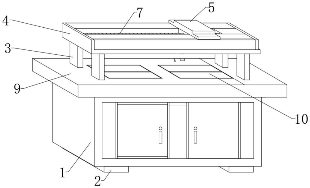
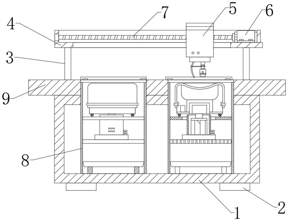
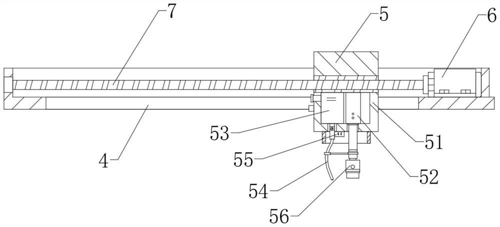
[0028] see Figure 1-4 , a metallographic preparation device for material science and engineering, comprising a box body 1, support feet 2 are installed on both sides of the lower end of the box body 1, a workbench 9 is fixedly installed on the upper end of the box body 1, and the four corners of the upper end of the workbench 9 are fixed Connected with support column 3, the upper end of support column 3 is fixedly connected with fixed seat 4, is slidably connected with sliding seat 5 on the fixed seat 4, and is threadedly connected with screw mandrel 7 on the inner upper part of slide seat 5, and one end of screw mandrel 7 avoids with the inner side of fixed seat 4. Rotate connection, the other end of the screw rod 7 is equipped with a motor one 6, and the motor one 6 is fixed on the lower end of the fixed seat 4; a telescopic rod 52 is installed in the lower part of the slide seat 5, and a mounting head 56 is fixedly installed on the lower end of the telescopic rod 52, and th...


PUM


Abstract

The invention relates to the technical field of material science and engineering, and discloses a metallographic preparation device for material science and engineering. The metallographic preparation device comprises a box body, supporting legs are mounted at the two sides of the lower end of the box body, and a worktable is fixedly mounted at the upper end of the box body; supporting columns are fixedly connected to the four corners at the upper end of the worktable, and a fixing seat is fixedly connected to the upper ends of the supporting columns. A sliding base is connected to the fixing seat in sliding manner, a lead screw is in threaded connection with the upper portion in the sliding seat, and one end of the lead screw is rotationally connected with the inner side wall of the fixing seat. According to the metallographic preparation device for material science and engineering, a cut metallographic sample is fixed through a mounting head, a first motor drives the lead screw to rotate, the lead screw acts on the sliding seat, the sliding seat drives a connecting base to move, and a telescopic rod in the connecting base and the metallographic sample fixed through the mounting head move together, and the metallographic sample is grinded and is automatically grinded and polished, so that the influence of fatigue of manual operation on the grinding of the metallographic sample is avoided, and the grinding and polishing of the metallographic sample are facilitated.

Description

technical field [0001] The invention relates to the technical field of material science and engineering, in particular to a metallographic preparation device for material science and engineering. Background technique [0002] Metallographic sample preparation is a very important part of metallographic research, which includes sample interception, sample inlay, sample polishing, sample polishing, and display of metallographic microstructure. Usually, the preparation of metallographic samples will go through the following steps: sampling, inlay (sometimes can be omitted), polishing (coarse grinding and fine grinding), polishing and corrosion. Every operation must be carried out carefully and strictly according to the operation requirements, because any operation error may affect the subsequent steps, and in extreme cases, it may also cause false tissue and thus draw wrong conclusions. Metallographic sample preparation is a technology closely related to the experience of the p...

Claims


Application Information

Patent Timeline
Patent Type & Authority Applications(China)
IPC IPC(8): G01N1/28G01N1/32
CPCG01N1/286G01N1/32
Inventor 邓轶凡陈心悦
Owner HOHAI UNIV
Why Eureka
Try Eureka