Computer chip packaging test equipment
A technology of chip packaging and testing equipment, which is applied in the direction of electronic circuit testing, measuring electricity, measuring devices, etc., can solve the problems of accidental pinching, difficult chip removal, etc., and achieve the effect of simple use, convenient operation, and reduced chip waste
- Summary
- Abstract
- Description
- Claims
- Application Information
AI Technical Summary
Problems solved by technology
Method used
Image
Examples
Embodiment 1
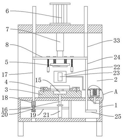
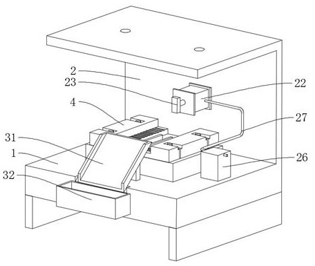
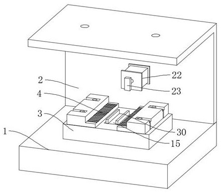
[0031] refer to Figure 1-6 , a kind of computer chip encapsulation and testing equipment, comprises workbench 1, also comprises: installation base 3, is fixedly connected on the workbench 1; On both sides, the mounting base 3 is slidingly connected with a push plate 15; the fixed frame 2 is fixedly connected to the workbench 1; wherein, the fixed frame 2 is fixedly connected with a second cylinder 22, and the output end of the second cylinder 22 is fixedly connected with a feeding plate 23; the fixed frame 2 is provided with a driving mechanism; wherein, the driving mechanism is fixedly connected with a current probe 5, the driving mechanism is connected with the push plate 15 through the jacking mechanism, and the driving mechanism is connected with the second cylinder 22 through the pushing mechanism .
[0032] In the present invention, when the user uses it, the chip is placed on the detection board 4, and then the driving mechanism is started, and the driving mechanism d...
Embodiment 2
[0034] refer to Figure 1-6, a kind of computer chip encapsulation and testing equipment, comprises workbench 1, also comprises: installation base 3, is fixedly connected on the workbench 1; On both sides, the mounting base 3 is slidingly connected with a push plate 15; the fixed frame 2 is fixedly connected to the workbench 1; wherein, the fixed frame 2 is fixedly connected with a second cylinder 22, and the output end of the second cylinder 22 is fixedly connected with a feeding plate 23; the fixed frame 2 is provided with a driving mechanism; wherein, the driving mechanism is fixedly connected with a current probe 5, the driving mechanism is connected with the push plate 15 through the jacking mechanism, and the driving mechanism is connected with the second cylinder 22 through the pushing mechanism .
[0035] The driving mechanism includes a first cylinder 6, a push rod 7 and a fixed plate 8, the first cylinder 6 is fixedly connected to the top of the fixed frame 2, the p...
Embodiment 3
[0040] refer to Figure 1-6 , compared with Embodiment 1, it is further that: the jacking mechanism includes a push rod 16, a first connecting rod 17, a tooth plate 18, a rotating rod 19, a ratchet 20 and a cam 21, and the push rod 16 is slidably connected to the mounting base 3 Above, the push plate 15 is fixedly connected to the ejector rod 16, the push plate 15 is located between the two groups of detection plates 4, the first connecting rod 17 is fixedly connected to the fixed plate 8, and the tooth plate 18 is fixedly connected to the first connecting rod 17 The rotating rod 19 is rotatably connected to the workbench 1, the ratchet 20 and the cam 21 are fixedly connected to the rotating rod 19, the ratchet 20 is meshed with the tooth plate 18, and the cam 21 is offset against the ejector rod 16.
[0041] Pushing mechanism comprises second connecting rod 24, driving plate 25, piston cylinder 26, outlet pipe 27, piston rod 28 and the 3rd spring 29, and second connecting rod...
PUM
 Abstract
Description
Claims
Application Information
 - R&D
- Intellectual Property
- Life Sciences
- Materials
- Tech Scout
- Unparalleled Data Quality
- Higher Quality Content
- 60% Fewer Hallucinations
Browse by: Latest US Patents, China's latest patents, Technical Efficacy Thesaurus, Application Domain, Technology Topic, Popular Technical Reports.
© 2025 PatSnap. All rights reserved.Legal|Privacy policy|Modern Slavery Act Transparency Statement|Sitemap|About US| Contact US: help@patsnap.com


