LED lamp bead

A technology of LED lamp beads and LED chips, applied in electrical components, circuits, semiconductor devices, etc., can solve the problems of silicone inflow, failure, and improve the difficulty of packaging silicone at the output end, and achieve the effect of improving convenience.

Active Publication Date: 2021-08-24
SHENZHEN AUROLED TECH
View PDF11 Cites 0 Cited by
  • Summary
  • Abstract
  • Description
  • Claims
  • Application Information

AI Technical Summary

Problems solved by technology

[0004] In view of the above-mentioned related technologies, the inventor believes that there are the following defects: the output end of the LED chip needs to be immersed in the packaging silica gel, and because the lamp bead base is small in size, t

Method used


Image

  • LED lamp bead
  • LED lamp bead
  • LED lamp bead

Examples


Example Embodiment

[0036] Example 1

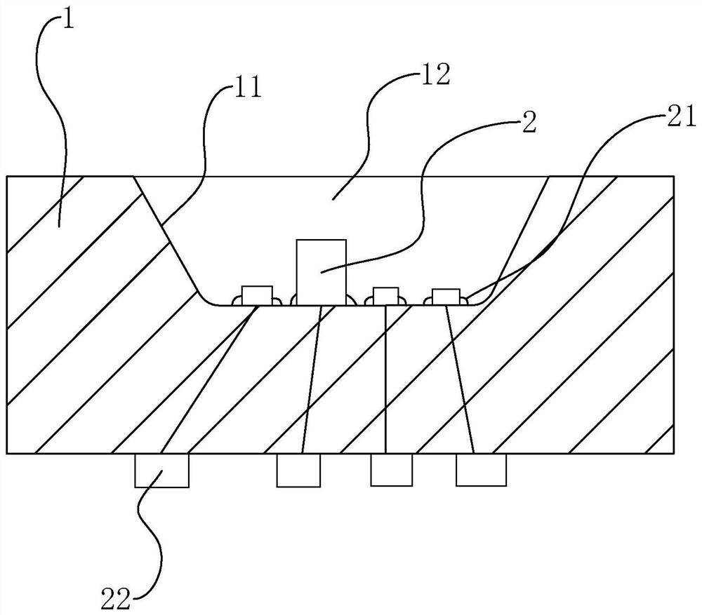
[0037] refer to figure 2 , The LED lamp bead includes a lamp bead base 1, and the lamp bead base 1 is made of glass fiber, mainly epoxy resin. The lamp bead base is in the shape of a cuboid.

[0038] refer to figure 2 , the top surface of the lamp bead base 1 is provided with an installation groove 11, the installation groove 11 is set as a conical shape with a narrow bottom and a wide top, the bottom end surface of the installation groove 11 is set as a plane parallel to the bottom surface of the lamp bead base 1, the top of the installation groove 11 The opening is flush with the top surface of the lamp bead base 1. The expansion of the notch at the top of the installation groove 11 facilitates the installation of the LED chip 2 at the bottom of the installation groove 11 .

[0039] refer to figure 2 , four groups of LED chips 2 are arranged in the installation groove 11, and the four groups of LED chips 2 are all LED lamp beads. Among them, the f...

Example Embodiment

[0047] Example 2

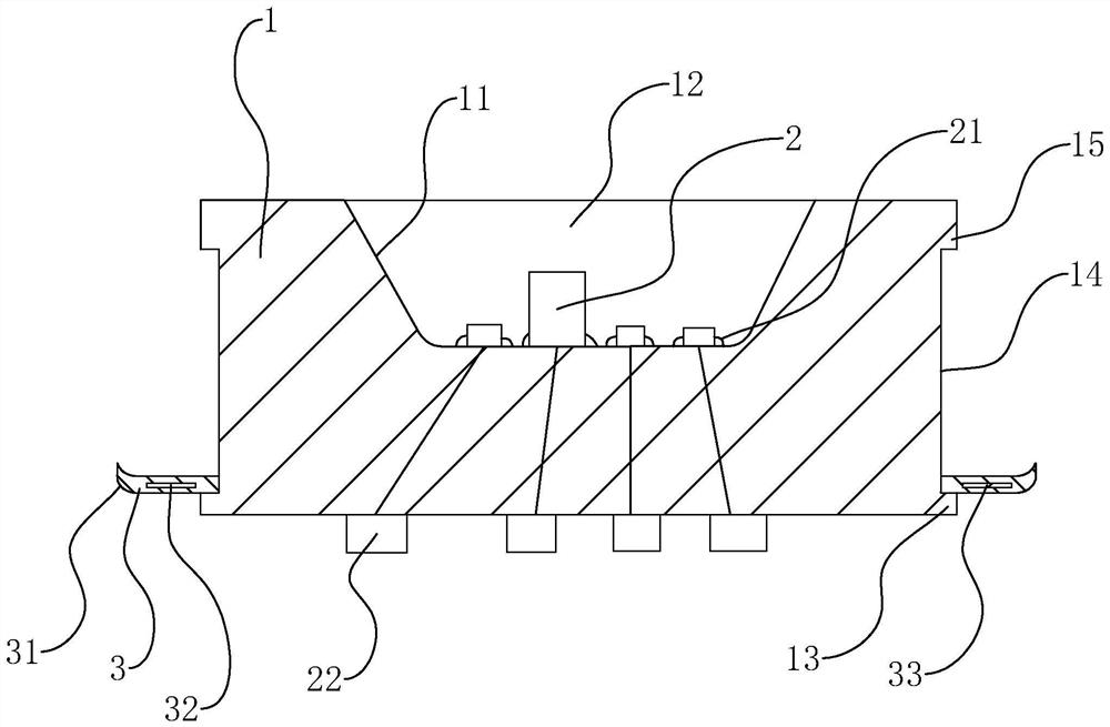
[0048] refer to image 3 The difference between embodiment 2 and embodiment 1 is that the lamp bead base 1 is provided with a sealing piece 3, the outer wall of the lamp bead base 1 is provided with a chute 14, and the length of the chute 14 is set to the outer circumference of the outer wall of the lamp bead base 1 Extending one circle, the width of the slide groove 14 is set to extend along the height of the lamp bead base 1 .

[0049] refer to image 3, the closure piece 3 is in the shape of a "mouth", and the closure piece 3 includes two pieces of the same shape. connected to form the closure piece 3. The inner wall of the sealing piece 3 fits closely with the groove bottom of the chute 14, the sealing piece 3 is arranged horizontally and its outer wall extends out of the chute 14, so that the outer peripheral surface of the sealing piece 3 exceeds the height of the lamp bead base 1 in the vertical direction. peripheral surface. When the bottom surf...


PUM


Abstract

The invention relates to an LED lamp bead, and relates to the technical field of lamps, the LED lamp bead comprises a lamp bead base, a mounting groove is formed in the top surface of the lamp bead base, an LED chip is fixed in the mounting groove, a packaging glue layer covering the LED chip is packaged in the mounting groove, the output end of the LED chip is arranged on the lamp bead base in a penetrating mode and arranged on the bottom surface of the lamp bead base, and protective glue is packaged at the output end of the LED chip. The LED packaging structure has the effect of facilitating silica gel packaging at the output end of the LED chip.

Description

technical field [0001] The present application relates to the technical field of lamps, in particular to an LED lamp bead. Background technique [0002] LED is a solid-state semiconductor device that can convert electrical energy into light energy. Environmental protection and other advantages. [0003] refer to figure 1 , the related technology discloses an LED lamp bead, including a lamp bead base, a mounting groove is opened on the lamp bead base, an LED chip is fixedly connected in the mounting groove, and the output end of the LED chip passes through the lamp bead base and is placed on the lamp bead base side wall. [0004] In view of the above-mentioned related technologies, the inventor believes that there are the following defects: the output end of the LED chip needs to be immersed in the packaging silica gel, and because the lamp bead base is small in size, the top surface of the lamp bead base is easily covered by the silica gel during the immersion packaging p...

Claims


Application Information

Patent Timeline
IPC IPC(8): H01L33/54H01L33/52H01L33/62
CPCH01L33/54H01L33/52H01L33/62
Inventor 蒋顺才张慧萍田丰
Owner SHENZHEN AUROLED TECH
Why Eureka
Try Eureka