Device and method for inhibiting differential system inflation airflow effect

A differential and airflow technology, applied in the direction of electrical components, accelerators, linear accelerators, etc., can solve problems such as quenching, and achieve the effect of solving airborne problems

Pending Publication Date: 2021-08-24
INST OF MODERN PHYSICS CHINESE ACADEMY OF SCI
View PDF0 Cites 0 Cited by
  • Summary
  • Abstract
  • Description
  • Claims
  • Application Information

AI Technical Summary

Problems solved by technology

However, theory and experiments have found that in the differential vacuum system, the gas molecules near the axis of the low vacuum level will pass through the subsequent differential tube without collision, and directly enter the front end of the inflated airflow direction, and then increase the differential number or pump

Method used


Image

  • Device and method for inhibiting differential system inflation airflow effect
  • Device and method for inhibiting differential system inflation airflow effect

Examples


Embodiment 1

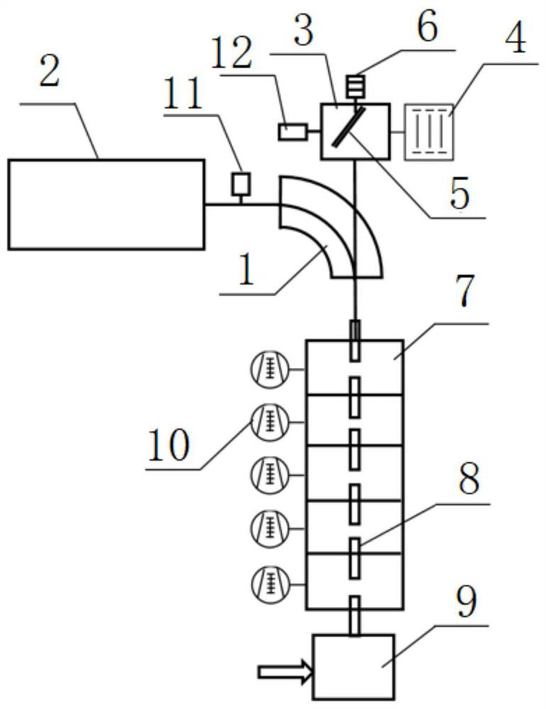
[0032] In this embodiment, a device for suppressing the gas flow effect of the differential system is provided, which is used for a differential vacuum system transitioning from low vacuum to ultra-high vacuum, and the gas gas flow effect is suppressed. Such as figure 1 As shown, the device includes a differential vacuum system, a deflection magnet, a vacuum chamber 1, a superconducting accelerator 2 and an extraction system. The output end of the differential vacuum system is connected to the deflection magnet and one end of the vacuum chamber 1 through the transmission pipeline; the other end of the deflection magnet and the vacuum chamber 1 is connected to the output end of the superconducting accelerator 2 through the transmission pipeline, and the output of the superconducting accelerator 2 is charged particle beam. An extraction system is arranged above the deflection magnet and the vacuum chamber 1 , and the input end of the extraction system communicates with the uppe...

Embodiment 2

[0046] In this embodiment, a method for suppressing the airflow effect of the differential system is provided, which is implemented based on the device in Embodiment 1, and includes the following steps:

[0047] Step 1, setting the angle of inclination of the spoiler 5, so that the angle of inclination of the spoiler 5 is the optimum suppression angle;

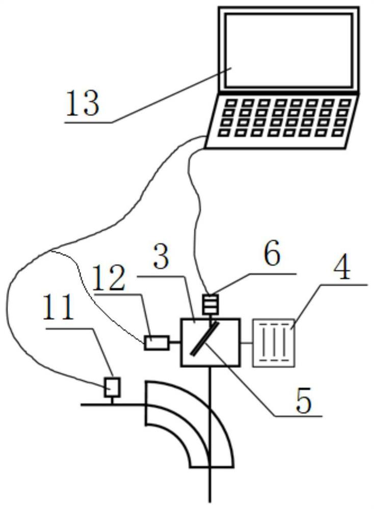
[0048] Specifically: the computer control system 13 adjusts the action of the spoiler drive motor 6 according to the vacuum value transmitted by the monitoring vacuum gauge 11 and the measuring vacuum gauge 12 to achieve the optimal suppression angle of the spoiler 5 . The adjustment method is:

[0049] Step 1.1, read the reading of the monitoring vacuum gauge 11, and give the spoiler drive motor 6 an initial positive direction (defining the clockwise direction along the direction of the inflated airflow as positive) step rotation angle in advance;

[0050] In this embodiment, the step rotation angle θ=1°.

[0051] Step 1.2,...


PUM


Abstract

The invention relates to a device for inhibiting an inflation airflow effect of a differential system. The output end of a differential vacuum system is connected with one end of a deflection magnet and one end of a vacuum chamber through a transmission pipeline; the other ends of the deflection magnet and the vacuum chamber are connected with the output end of the superconducting accelerator through a transmission pipeline; a the superconducting accelerator is used for outputting charged particle beams; and an extraction system is arranged above the deflection magnet and the vacuum chamber, and the input end of the extraction system is communicated with the deflection magnet and the upper portion of the middle of the vacuum chamber through a transmission pipeline. The invention further relates to a method for restraining the inflation airflow effect of the differential system, and the method comprises the steps that the inclination angle of the spoiler is set to be the optimal restraining angle; a beam output by a superconducting accelerator is deflected by a deflection magnet and a vacuum chamber and then enters a differential vacuum system, and He gas output by a differential pipeline enters a collection vacuum chamber through the deflection magnet and the vacuum chamber; and the He gas flow collected in the collection vacuum chamber is disturbed by a spoiler and then is pumped out by a three-pole sputtering ion pump.

Description

technical field [0001] The invention relates to the field of a superconducting accelerator and nuclear physics, in particular to a device and method for suppressing the effect of gas flow in a differential system. Background technique [0002] The superconducting linear accelerator (CiADS) transmits the beam to the gas-filled recoil spectrometer (SHANS2) of the terminal for nuclear physics experiments. On the one hand, SHANS2 needs to maintain an 80Pa He atmosphere in the experimental terminal, on the other hand, it is in an ultra-high vacuum (10 -7 Pa) In order to avoid quenching of the superconducting cavity, a large amount of air is prohibited from entering the superconducting accelerator. Therefore, a vacuum device—a differential vacuum system—is needed to complete the transition from low vacuum to ultrahigh vacuum. However, theory and experiments have found that in a differential vacuum system, gas molecules near the axis of the low vacuum level will pass through the ...

Claims


Application Information

Patent Timeline
IPC IPC(8): H05H7/20H05H7/00H05H9/00H05H7/22
CPCH05H7/20H05H7/001H05H9/00H05H7/22H05H2007/002H05H2007/046Y02E30/10
Inventor 柴振焦纪强蒙峻刘建龙张志远罗成谢文君马向利朱小荣李长春
Owner INST OF MODERN PHYSICS CHINESE ACADEMY OF SCI
Why Eureka
Try Eureka