Demodulation circuit, demodulation method, and transmission device

A technology of demodulation circuit and demodulation method, which is applied in the direction of electrical components, selective content distribution, broadcast transmission system, etc., and can solve problems such as lengthy and complex formats

Pending Publication Date: 2021-08-24
SONY SEMICON SOLUTIONS CORP
View PDF5 Cites 0 Cited by
  • Summary
  • Abstract
  • Description
  • Claims
  • Application Information

AI Technical Summary

Problems solved by technology

Therefore, even when the interface for receiving the synthesized variable-length packet is an LSI included in the receiver, since t

Method used


Image

  • Demodulation circuit, demodulation method, and transmission device
  • Demodulation circuit, demodulation method, and transmission device
  • Demodulation circuit, demodulation method, and transmission device

Examples


no. 1 Embodiment approach

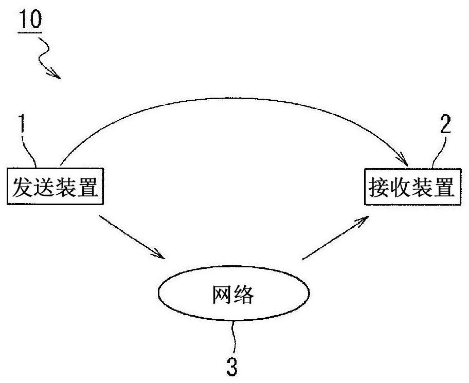
[0021] like figure 1 As shown, the transmitting device 1 constitutes a broadcasting system 10 together with the receiving device 2 and the network 3 .

[0022] The broadcast system 10 is a system related to digital cable television broadcasting.

[0023] The transmitting device 1 is a device on the side of a broadcasting station that performs digital cable TV broadcasting.

[0024] The receiving device 2 receives broadcast waves transmitted from the transmitting device 1 via the network 3 . In addition, the transmission via the network 3 can also be the transmission of information related to the broadcast content.

[0025] Broadcast waves transmitted from the transmitting device 1 are transmitted in a format called MMT (MPEG Media Transport) or TLV (Type Length Value) format, and are received by the receiving device 2 .

[0026] The MMT and TLV methods are methods in which video signals, voice signals, and control signals are stored and transmitted in IP (Internet Protocol)...


PUM


Abstract

This transmission device is provided with: a demodulation circuit that consolidates a plurality of TMCC signals being arranged, in a dispersed manner, in a frame containing TMCC signals and a main signal transmitted in a state of being superposed on a broadcast wave, that outputs the consolidated TMCC signals either before or after the main signal, and that individually demodulates the main signal and the TMCC signals for the frame so as to generate a variable-length packet containing the main signal and the TMCC signals; and a cable retransmission conversion unit which performs, for use in cable broadcasting, QAM modulation on a demodulated signal demodulated by the demodulation circuit.

Description

technical field [0001] The technology (this technology) related to this disclosure relates to a demodulation circuit for receiving and demodulating a main signal and a TMCC signal transmitted superimposed on a broadcast wave, a demodulation method using a demodulation circuit, and a transmission device including a demodulation circuit . Background technique [0002] As a technique used for signal processing such as digital broadcasting, for example, as disclosed in Patent Document 1, variable-length data is transmitted using a signal line between a processing unit that performs demodulation processing and a processing unit that performs demultiplexing processing. Bag. [0003] Patent Document 1: International Publication No. 2016 / 199603 [0004] However, in the technique disclosed in Patent Document 1, Ethernet (registered trademark) is assumed as an interface for combining and receiving variable-length packets output from a plurality of broadcasting stations. Therefore, ...

Claims


Application Information

Patent Timeline
IPC IPC(8): H04H20/78H04H20/95H04N21/435H04N21/438H04N21/647
CPCH04H20/78H04N21/435H04H20/95H04N21/438H04N21/647
Inventor 平山雄一
Owner SONY SEMICON SOLUTIONS CORP
Why Eureka
Try Eureka