
Mapping method of code word with QAM modulation

a code word and modulation technology, applied in the field of communication systems, can solve the problems of steep error rate characteristic, interleaving deterioration of error rate characteristic, etc., and achieve the effect of minimizing the error rate and good results

Active Publication Date: 2007-10-02
MAXELL HLDG LTD
View PDF16 Cites 26 Cited by
  • Summary
  • Abstract
  • Description
  • Claims
  • Application Information

AI Technical Summary

Benefits of technology

The invention is a communication method using a multi-level modulation system, which involves coding and modulating data, selectively rearranging the data, and demodulating and decoding the data. The method uses a mapping system that assigns bits of the data to symbols based on their resistance to error. The system calculates the signal-to-noise ratio (S / N) ratio and makes mapping processing accordingly to minimize errors. The technical effects of the invention include improved transmission and reception of data, reduced errors, and improved performance in low signal-to-noise ratio environments.

Problems solved by technology

The interleaving process can cause the error rate characteristic to have steepness peculiar to the turbo code in the high S / N region.
In the low S / N region, however, the interleaving deteriorates the error rate characteristic.
Thus, after detailed examination of the error rate characteristics in the prior art, the following problems have been found.
In the conventional radio communication system, since the fixed mapping method with no interleaver is used in which each code word bits are every time assigned to the same bits of QAM, the communication quality of each code word is changed, thus causing the error rate characteristic deterioration shown in FIG. 8.
In addition, the conventional system has the drawback that the code word mapping method cannot be changed according to the situation of propagation path and S / N.
Moreover, in the conventional system, the code word mapping method does not consider the level of importance of code word for decoding and the resistance of QAM bits to error, and thus satisfactory error rate characteristics cannot be achieved in all S / N regions.

Method used


Image

  • Mapping method of code word with QAM modulation
  • Mapping method of code word with QAM modulation
  • Mapping method of code word with QAM modulation

Examples


first embodiment

[0085]the invention will be described.

[0086]FIG. 12 is a block diagram showing the construction of a radio communication system according to the invention. In a transmission-side radio communication apparatus 1201, unlike the conventional one, the receiver 109 receives S / N information 1206 from the current propagation path, and there are also provided a mapping method decision unit 1205 for decision of a mapping method according to this value, and a switch 1204 for switching an interleaver 1004 and its bypass. In addition, in a receiving-side radio communication apparatus 1202, a mapping method decision unit 1209 and switch 1208 are provided for switching mapping method in synchronism with the S / N information 1210 used in the transmission-side apparatus.

[0087]In this system, the transmission-side apparatus 1201, when the S / N is in a low region, does not make interleaving, but maps the code word into QAM bits without interleaving, and when the S / N is in a high region, it makes interl...

tenth embodiment

[0088]When a turbo code of, for example, coding rate R=⅓ and 64 QAM are used as a coding method, the interleaving process is not made when the S / N is smaller than 7.5 dB, but is performed by switching when the S / N is larger than 7.5 dB as illustrated in FIG. 13, so that the operation can be made at a satisfactory error rate even if the S / N is in any region as shown in FIG. 13 by the bold line. This embodiment can be applied not only to the example of FIG. 13, but also to any combination of other coding methods, other coding rates and other multi-level QAM. The S / N measuring method in the receiving-side apparatus and the S / N information acquisition method in the transmitting-side apparatus will be described in detail in the tenth embodiment section given later.

second embodiment

[0089]the invention will be described next.

[0090]FIG. 21 is a flowchart for the process in the mapping decision unit.

[0091]This embodiment considers the case where the transmission-side apparatus and receiving-side apparatus in FIG. 13 of the first embodiment are placed under the closed-loop transmission power control so that the power is controlled constant at around S / N=7.5 dB or that the situation of the radio propagation path is substantially kept constant around S / N=7.5 dB. In this case, in the first embodiment, since the interleaving operation is switched on or off, or present or absent according to the reference value of S / N=7.5 dB, the frequency of the switching for interleaving inevitably increases. However, when the S / N is around 7.5 dB, there is almost no error rate characteristic difference between the interleaving operation and not interleaving operation as will be apparent from FIG. 13. Therefore, an S / N interval of no switching control is provided as shown in FIG. 21....


PUM


Abstract

In the code word mapping operation of a radio communication system, mapping patterns are provided for different S / N ratios, the code word bits produced from a coder are not equally assigned to multi-level modulation bits, but weighted according to the resistance of multi-level modulation bits to error before being assigned, and the mapping patterns are switched in accordance with S / N. Since the code word mapping method is updated so that the error rate can be always minimized according to the situations of a propagation path and S / N ratio, communication can be made with high communication quality.

Description

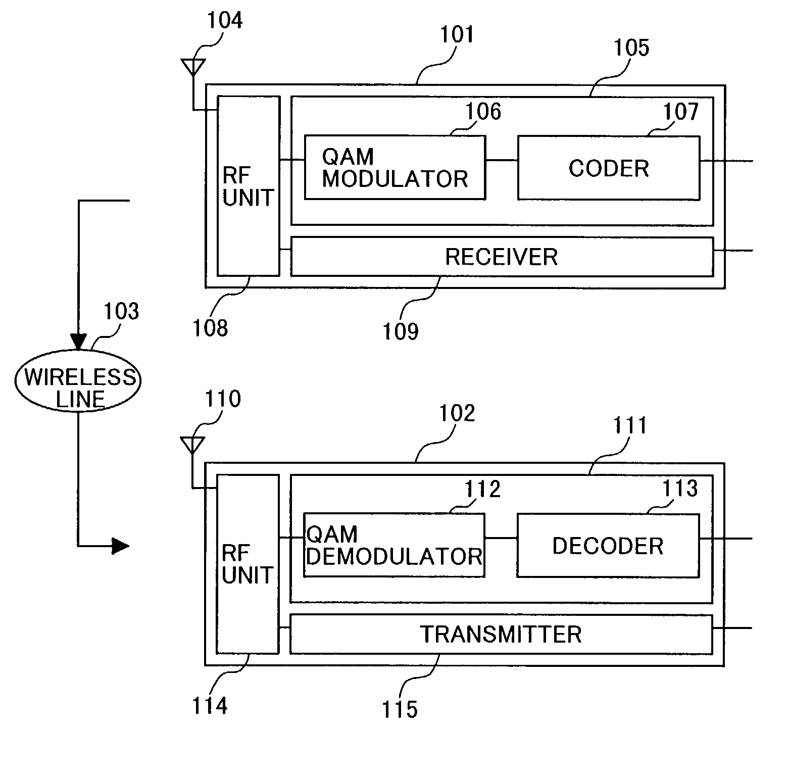
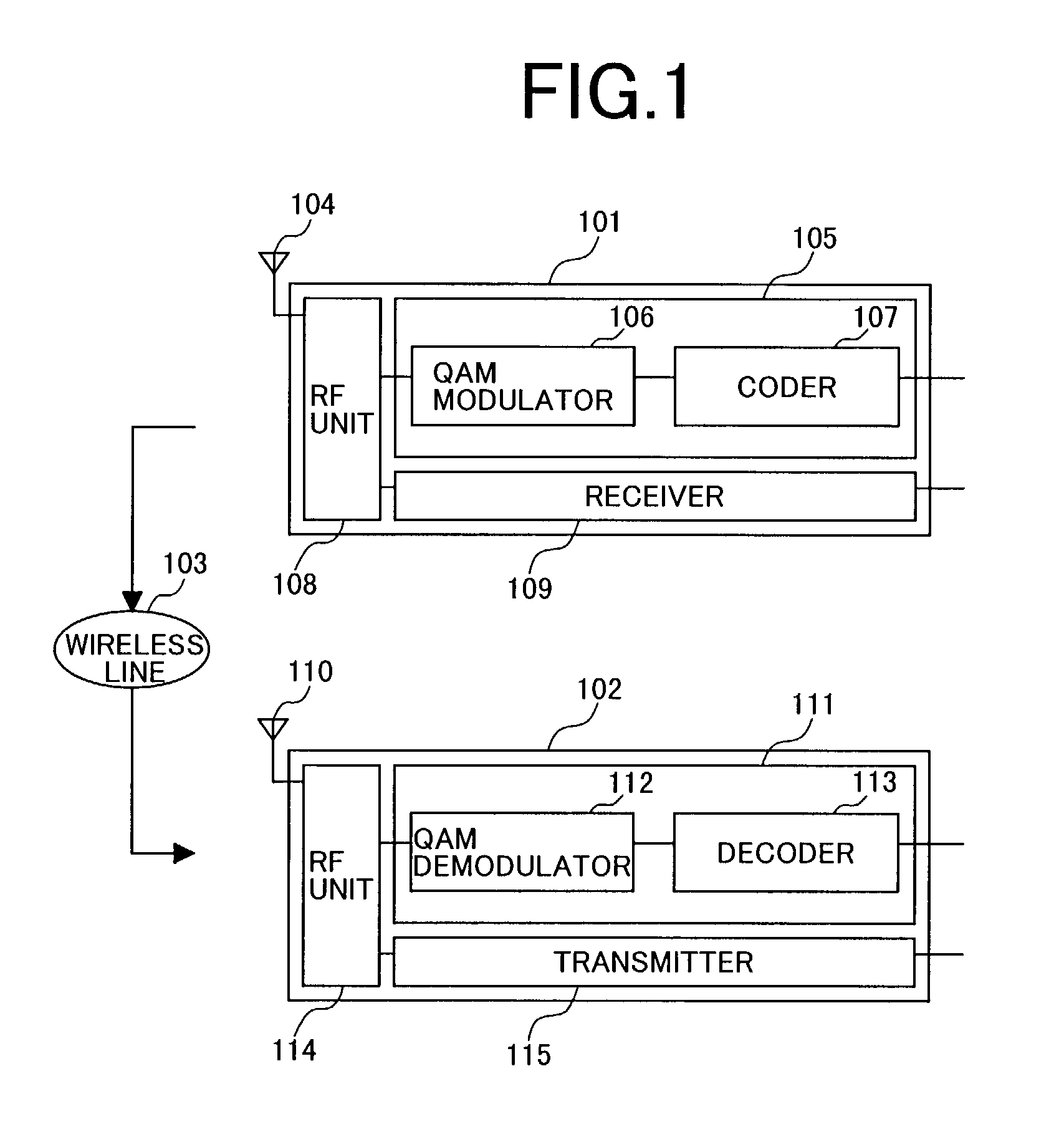
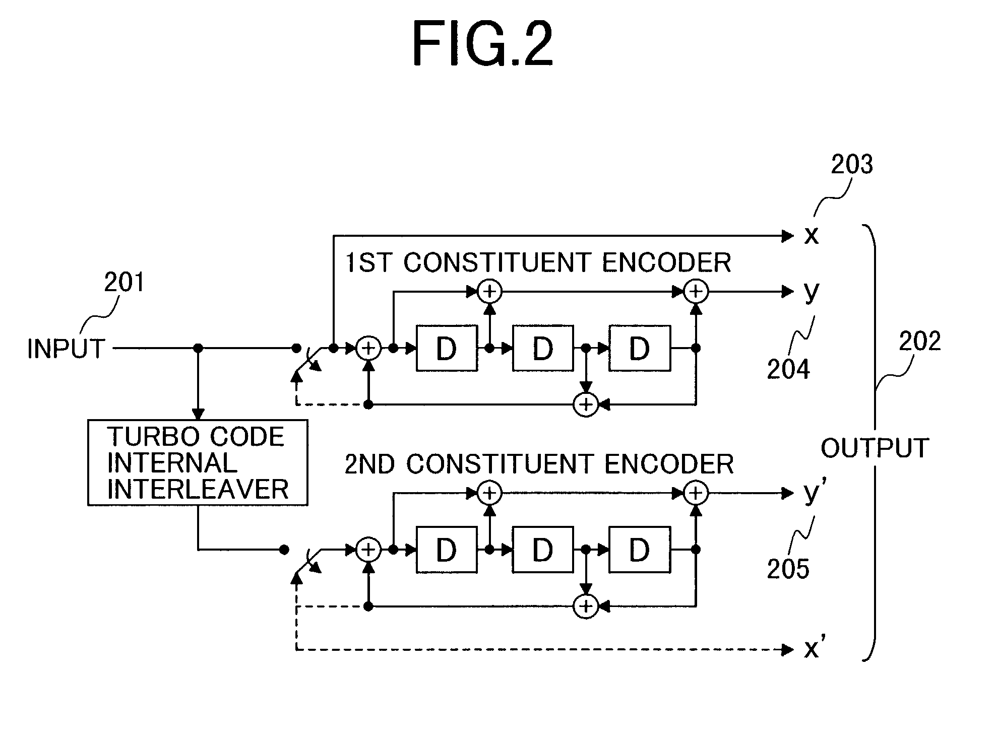
BACKGROUND OF THE INVENTION[0001]The present invention generally relates to a communication system, and particularly to a mapping method of code word in radio communication apparatus used in a radio communication system.[0002]FIG. 1 is a block diagram of the constructions of conventional radio communication apparatus and radio communication system. The radio communication system is formed of a transmission-side radio communication apparatus 101 and a receiving-side radio communication apparatus 102 between which messages and data are transmitted through a radio propagation path 103. Although in FIG. 1 and all the following drawings one channel (for example, downlink) is given as an example, the same is true of uplink.[0003]In the transmission-side radio communication apparatus 101, the data to be transmitted is first encoded by a coder 107 within a transmitter 105. In radio communication, convolutional coding and turbo coding are often used as coding methods. The coded words, or cod...

Claims


Application Information

Patent Timeline
Patent Type & Authority Patents(United States)
IPC IPC(8): H03K9/00H04L27/00H04L1/00H04L27/34
CPCH04L1/0003H04L1/0009H04L1/0042H04L27/3416H04L1/0066H04L1/0047H04L1/0016H04L1/0067H04L1/0071
Inventor HANAOKA, SEISHIYANO, TAKASHI
Owner MAXELL HLDG LTD
Learn More