
Honey extractor capable of preventing honeycomb honey chippings from flowing out and preventing honey from remaining

A technology of honeycomb honey and honey shaker, which is applied in the field of honey shaker, which can solve the problems of turbidity processing, affecting honey output efficiency, impact, etc., and achieve the effect of accelerating the outflow efficiency

Inactive Publication Date: 2021-08-27
廖文朵
View PDF0 Cites 0 Cited by
  • Summary
  • Abstract
  • Description
  • Claims
  • Application Information

AI Technical Summary

Problems solved by technology

[0002] With the improvement of people's quality of life, honey and its related products are deeply loved by people because of their certain maintenance effects. Honeycomb honey is the natural state of honey, which is obtained by beekeepers by raising bees for honey collection. For honeycomb Honey needs to use a honey shaker to centrifuge the honey in the honeycomb honey to make the honey flow out, while other impurities and crystal residues in the honeycomb honey can be separated, but during the honey shaking process, the debris in the honeycomb honey will follow some The honey flows out into the honey slurry, causing the turbidity of the honey slurry to affect the subsequent processing, and the remaining debris and crystals that are separated often leave some honey as waste, resulting in waste and affecting the output efficiency of honey

Method used


Image

  • Honey extractor capable of preventing honeycomb honey chippings from flowing out and preventing honey from remaining
  • Honey extractor capable of preventing honeycomb honey chippings from flowing out and preventing honey from remaining
  • Honey extractor capable of preventing honeycomb honey chippings from flowing out and preventing honey from remaining

Examples


Embodiment Construction

[0025] Combine below Figure 1-6 The present invention is described in detail, wherein, for the convenience of description, the orientations mentioned below are defined as follows: figure 1 The up, down, left, right, front and back directions of the projection relationship itself are the same.

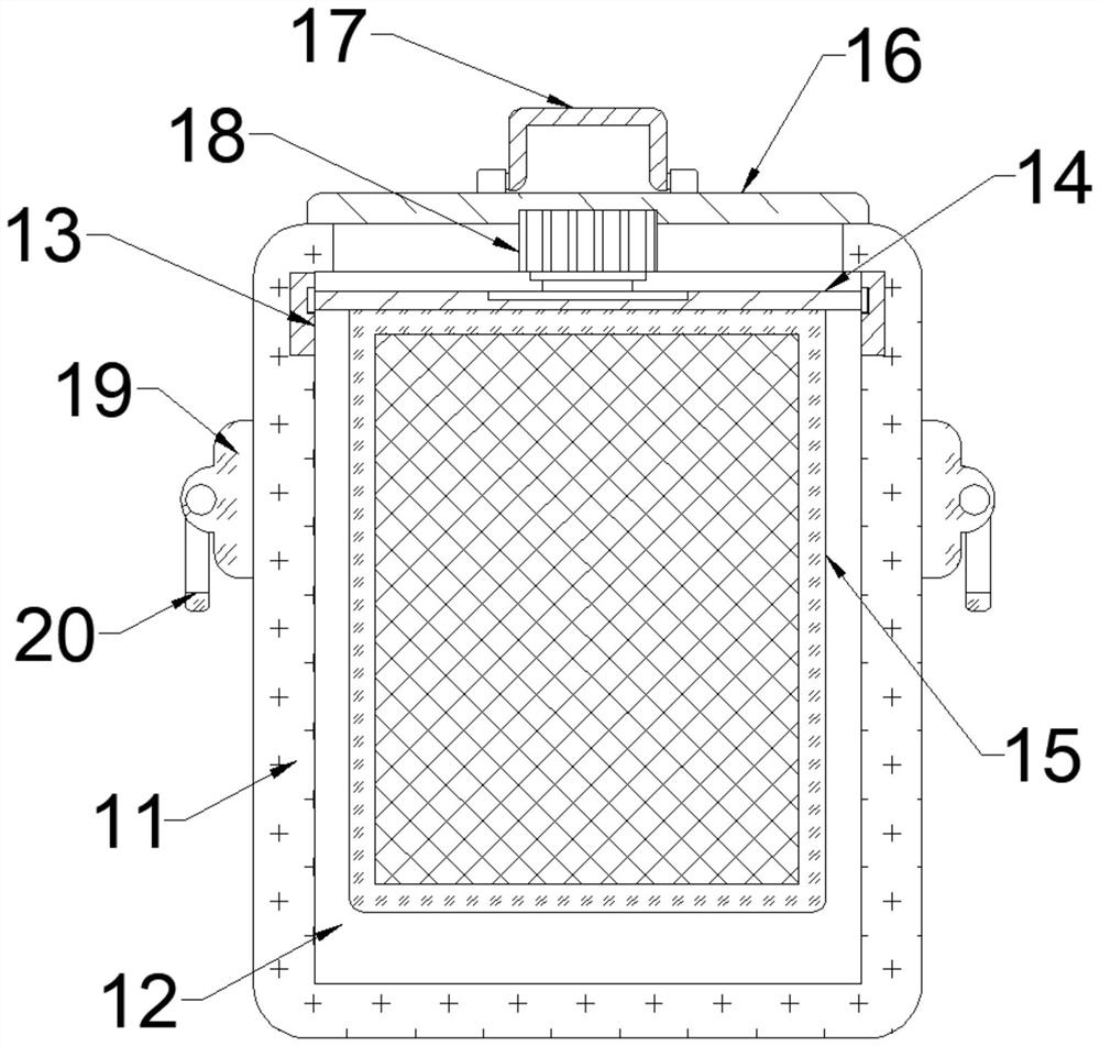
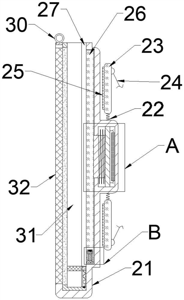
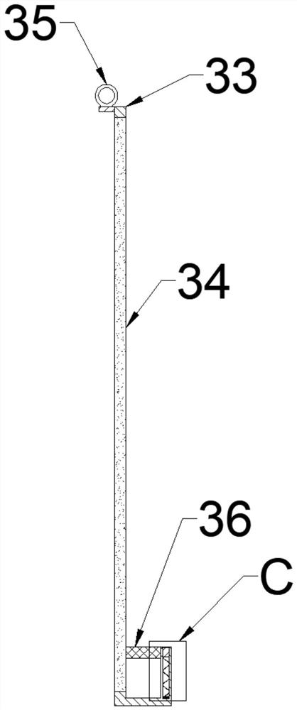
[0026] A honey shaker that can avoid the outflow of honeycomb honey fragments and honey residues described in conjunction with accompanying drawings 1-6 includes a honey shaker bucket 11, a honey chamber 12 is provided in the honey shaker bucket 11, and the honey chamber 12 An adapter ring 13 is fixedly installed inside the adapter ring 13, and a power rotating rod 14 is rotatably installed inside the adapter ring 13. A deliberation honey shaking device 15 is detachably installed on the lower side of the power rotating rod 14. The deliberation honey shaking device 15 Including a honey shaking plate 21, the honey shaking plate 21 is provided with a honey shaking cavity 31, the inner wa...


PUM


Abstract

The invention relates to the related technical field of honey processing, and discloses a honey extractor capable of preventing honeycomb honey chippings from flowing out and preventing honey from remaining. The honey extractor comprises a honey extracting barrel; a honey cavity is formed in the honey extracting barrel; an adapter ring is fixedly installed in the honey cavity; a power rotating rod is rotatably installed in the adapter ring; a pushing and knocking honey extracting device is detachably mounted on the lower side of the power rotating rod; the pushing and knocking honey extracting device comprises a honey extracting plate; a honey extracting cavity is formed in the honey extracting plate; a functional groove is formed in the inner wall of the right side of the honey extracting cavity; and a pushing and squeezing plate is slidably mounted in the functional groove. According to the honey extractor capable of preventing the honeycomb honey chippings from flowing out and preventing the honey from remaining, through the arrangement of the pushing and knocking honey extracting device, the honey in the pushing and knocking honey extracting device containing honeycomb honey flows out into the honey cavity through a leakage net plate under the rotation of a centrifugal motor; and in the centrifugal honey extracting process, through the arrangement of an internal debris treatment device, debris in the honey is intercepted.

Description

technical field [0001] The invention relates to the technical field related to honey processing, in particular to a honey shaker capable of avoiding the outflow of honeycomb honey debris and honey residue. Background technique [0002] With the improvement of people's quality of life, honey and its related products are deeply loved by people because of their certain maintenance effects. Honeycomb honey is the natural state of honey, which is obtained by beekeepers by raising bees for honey collection. For honeycomb Honey needs to use a honey shaker to centrifuge the honey in the honeycomb honey to make the honey flow out, while other impurities and crystal residues in the honeycomb honey can be separated, but during the honey shaking process, the debris in the honeycomb honey will follow some The honey flows out into the honey slurry, causing the turbidity of the honey slurry to affect the subsequent processing, and the remaining debris and crystals that are separated often ...

Claims


Application Information

Patent Timeline
Patent Type & Authority Applications(China)
IPC IPC(8): A01K59/00A01K59/04
CPCA01K59/00A01K59/04
Inventor 廖文朵
Owner 廖文朵
Learn More