Concrete-filled steel structural support columns

A steel structure and support column technology, applied in the field of steel structure support columns, can solve problems affecting structural strength, etc., and achieve the effects of ensuring structural strength, reducing the number of cavities, and slowing down the falling speed

Active Publication Date: 2022-03-29
浙江高盛钢结构有限公司
View PDF23 Cites 0 Cited by
  • Summary
  • Abstract
  • Description
  • Claims
  • Application Information

AI Technical Summary

Problems solved by technology

[0003] When filling, the concrete slurry falls freely in the support column, causing air to be mixed into the concrete slurry. After it solidifies, there are more cavities in the concrete, which will affect its structural strength.

Method used


Image

  • Concrete-filled steel structural support columns
  • Concrete-filled steel structural support columns
  • Concrete-filled steel structural support columns

Examples


Embodiment 1

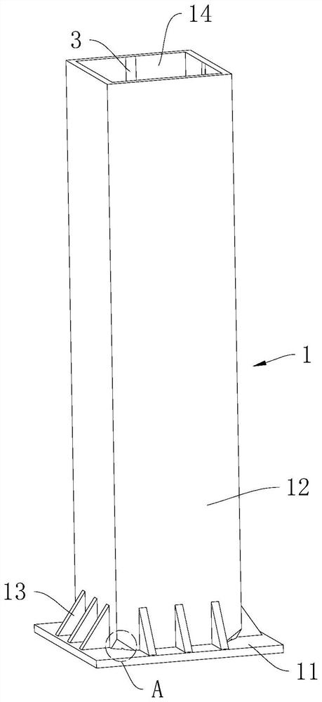
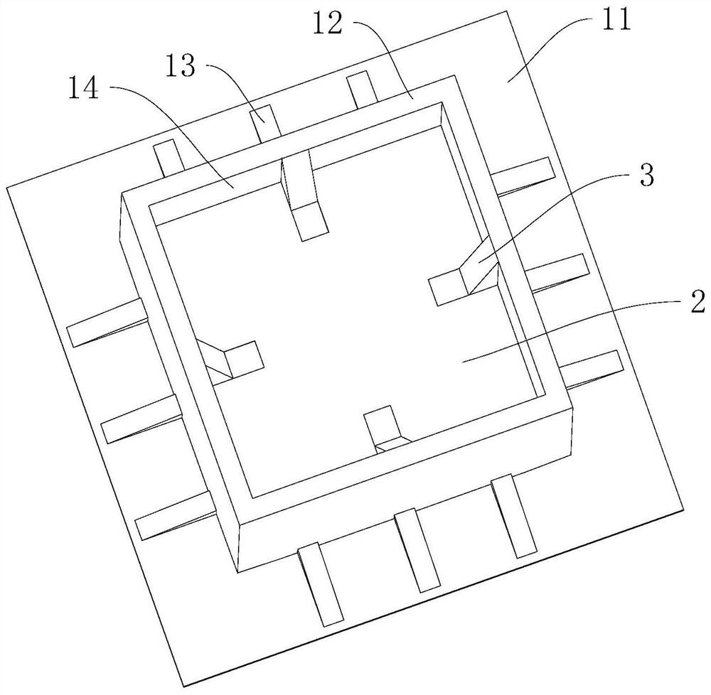
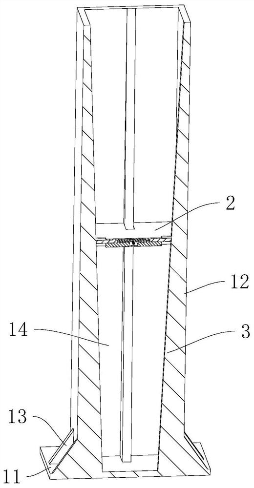
[0044] refer to figure 1 , 2 , the steel structure support column filled with concrete includes a column body 1 and a buffer plate 2 .

[0045] The column body 1 includes a bottom plate 11 , side plates 12 and reinforcing ribs 13 . The base plate 11 is horizontal, and the lower surface of the base plate 11 is used to contact the ground; the side plates 12 are vertically arranged, and the lower ends of the side plates 12 can be fixedly connected to the upper surface of the base plate 11 by welding; at the same time, the four side plates 12 pass The way of welding is enclosed into a rectangle; then a filling cavity 14 is formed above the bottom plate 11 and between the four side plates 12, and the filling cavity 14 is used for concrete filling. The reinforcing rib 13 is connected to the upper surface of the bottom plate 11 by welding, and the reinforcing rib 13 is connected to the lower end of the outer surface of the side plate 12 facing away from the filling cavity 14 to imp...

Embodiment 2

[0061] refer to Image 6 , the difference between this embodiment and embodiment 1 is that

[0062] Two mounting holes 22 are provided and run through the buffer plate 2 , and the two mounting holes 22 are at the same height.

[0063] The friction part 41 can be made of materials that are easy to wear such as rubber; the pressing part 42 uses a magnet 422, and the magnet 422 and the support member 3 can be attracted to each other by magnetic force; Mutual repulsion, so that the two opposite pressing pieces 4 have a tendency to move away from each other.

[0064] The implementation principle of Embodiment 2 is: as the concrete slurry is continuously injected into the filling cavity 14, the downward force exerted by the concrete slurry on the buffer plate 2 increases continuously; The support 3 moves down synchronously. On the one hand, the sliding friction between the friction part 41 and the friction surface 31 makes the friction part 41 wear, and the distance between the ma...

Embodiment 3

[0066] refer to Figure 7 , 8 , the difference between this embodiment and embodiment 1 is that

[0067] The pressing member 4 is fixedly connected to the buffer plate 2 and is located in the avoidance groove 21, and the thickness of the pressing member 4 decreases as it approaches the support member 3; and, the pressing member 4 moves down with the buffer plate 2 relative to the support member 3 At this time, the edge of the support member 3 cuts the resisting member 4, so that the resisting member 4 and the buffer plate 2 are sheared and fractured at the inner wall of the escape groove 21 .

[0068] The implementation principle of Embodiment 3 is: when the edge of the supporting member 3 cuts the pressing member 4, the thicker the pressing member 4 is, the greater the force required for cutting, the greater the corresponding reaction force, and the reaction force That is, the resistance received by the pressing member 4; then the resistance received by the pressing member ...


PUM


Abstract

This application relates to a steel structure support column filled with concrete, which includes a column body and a buffer plate; a filling cavity is provided in the column body, and the filling cavity penetrates the column body upwards; the buffer plate is vertically slid on the In the filling cavity; the peripheral side of the buffer plate is slidably attached to the inner wall of the filling cavity to form a friction pair; the main body is also provided with a vent hole; and at least one of the vent holes communicates with the bottom of the filling cavity. Before filling the concrete slurry into the column, the buffer plate is first embedded in the filling cavity and located at the opening; then, the concrete slurry is injected into the filling cavity, and the concrete slurry exerts a downward force on the buffer plate under the action of gravity. In this process, the friction between the peripheral side of the buffer plate and the inner wall of the filling cavity hinders the downward movement of the buffer plate, thereby slowing down the falling speed of the concrete slurry, which is beneficial to reduce the mixing The air in the concrete slurry can reduce the number of cavities in the concrete and ensure its structural strength.

Description

technical field [0001] The present application relates to the field of steel structures, in particular to a steel structure support column filled with concrete. Background technique [0002] At present, in order to improve the strength of the supporting column of the steel structure, the supporting column is usually filled with concrete. [0003] When filling, the concrete slurry falls freely in the support column, causing air to be mixed into the concrete slurry. After it solidifies, there are more cavities in the concrete, which affects its structural strength. Contents of the invention [0004] In order to reduce the number of cavities in concrete and ensure its structural strength, the application provides a steel structure support column filled with concrete. [0005] A steel structure support column filled with concrete provided by the application adopts the following technical scheme: [0006] A steel structure support column filled with concrete, including a colu...

Claims


Application Information

Patent Timeline
Patent Type & Authority Patents(China)
IPC IPC(8): E04C3/32E04C3/34
CPCE04C3/32E04C3/34
Inventor 赵红运李之强黎洪
Owner 浙江高盛钢结构有限公司
Why Eureka
Try Eureka