
Biomass energy mixed solid fuel efficient combustion device

A biomass energy and solid fuel technology, which is applied in the combustion, combustion method, combustion equipment and other directions of solid fuel, can solve the problems of inconvenient and efficient combustion, small combustion surface, and direct smoke emission, so as to increase the spreading degree and satisfy the use of demand, the effect of increasing the contact area

Pending Publication Date: 2021-08-27
徐州永路生物质能源有限公司
View PDF0 Cites 0 Cited by
  • Summary
  • Abstract
  • Description
  • Claims
  • Application Information

AI Technical Summary

Problems solved by technology

The existing device has the advantages of being able to crush the fixed biomass fuel and can filter the smoke generated by combustion, which solves the problem that the existing biomass solid fuel combustion device cannot crush the biomass solid fuel. The biomass energy fixed fuel cannot be fully burned, and a large amount of smoke is generated. At the same time, the biomass energy fixed fuel is wasted, and the smoke generated by combustion is directly discharged, which affects people's life and reduces the applicability of the biomass solid fuel combustion device.
[0004] The existing device sends the pulverized fuel to the combustion chamber through the material guide mechanism for combustion. However, in the existing device, because the solid fuel is dotted, the fuel sent to the combustion chamber is piled up together, and the combustion surface is small. , not easy to achieve efficient combustion

Method used


Image

  • Biomass energy mixed solid fuel efficient combustion device
  • Biomass energy mixed solid fuel efficient combustion device
  • Biomass energy mixed solid fuel efficient combustion device

Examples


Embodiment Construction

[0023] Embodiments of the present patent are described in detail below, examples of which are shown in the drawings, wherein the same or similar reference numerals designate the same or similar elements or elements having the same or similar functions throughout. The embodiments described below by referring to the figures are exemplary and are only used for explaining the patent, and should not be construed as limiting the patent.

[0024] In the description of this patent, it is to be understood that the terms "center", "upper", "lower", "front", "rear", "left", "right", "vertical", "horizontal", The orientation or positional relationship indicated by "top", "bottom", "inner", "outer", etc. is based on the orientation or positional relationship shown in the drawings, and is only for the convenience of describing this patent and simplifying the description, rather than indicating or implying References to devices or elements must have a particular orientation, be constructed, ...


PUM


Abstract

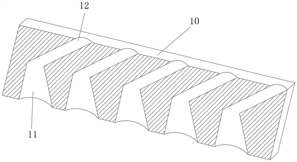
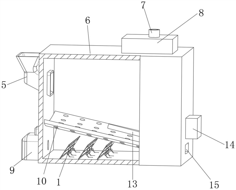
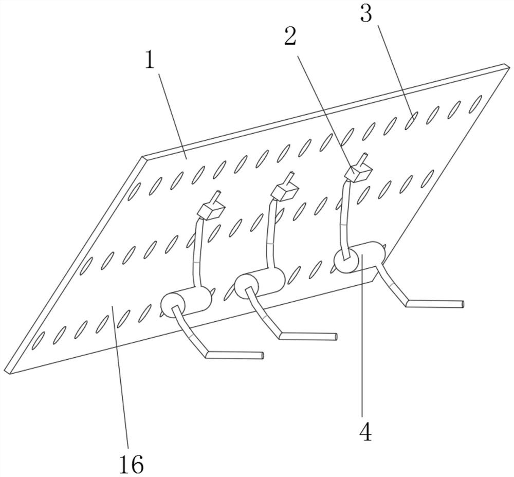
The invention discloses a biomass energy mixed solid fuel efficient combustion device. The biomass energy mixed solid fuel efficient combustion device comprises a combustion chamber, wherein a feeding hopper is arranged on one side of the combustion chamber, a pulverizer is arranged inside the feeding hopper, the pulverizer is used for crushing comburent entering the combustion chamber through the feeding hopper, an igniter is arranged on the outer wall of one side of the combustion chamber, a filtering chamber is arranged on the outer wall of the top of the combustion chamber, moreover, an air outlet pipe is arranged at the top of the filtering chamber in a communicating mode, an inclined plate is arranged at the bottom end of the interior of the combustion chamber, moreover, the two sides of the inclined plate are wound towards the middle, and one end, close to the feeding hopper, of the inclined plate is higher than the other end of the inclined plate. According to the biomass energy mixed solid fuel efficient combustion device, during use, solid fuel falling from the feeding hopper can be spread on the surface of the inclined plate, so that the phenomena that the contact surface is small and the combustion efficiency is low in a traditional device are solved; and for the solid fuel with the relatively light weight, the spreading degree of the solid fuel can be increased through air blown out from flow guide holes, and the contact area is further increased.

Description

technical field [0001] The invention relates to the technical field of combustion devices, in particular to a biomass energy mixed solid fuel high-efficiency combustion device. Background technique [0002] Biomass fuel refers to the burning of biomass materials as fuel, generally mainly agricultural and forestry waste. The main difference is that it is different from fossil fuels. In the current national policy and environmental protection standards, direct combustion of biomass is a highly polluting fuel, which is only used in large stoves in rural areas and is not allowed to be used in cities. The application of biomass fuels is actually mainly biological Material molding fuel is a new type of clean fuel that can be directly burned by using agricultural and forestry waste as raw materials and making various moldings through crushing, mixing, extrusion, drying and other processes. [0003] An existing biomass solid fuel combustion device includes a box body, a water inlet...

Claims


Application Information

Patent Timeline
Patent Type & Authority Applications(China)
IPC IPC(8): F23B30/00F23L1/00
CPCF23B30/00F23L1/00
Inventor 李宁刘梵赵俊铨
Owner 徐州永路生物质能源有限公司
Learn More