

Indoor foundation soil preparation device capable of keeping on-site stress state and preparation method thereof
A technology of stress state and preparation device, which is applied in the field of geotechnical engineering and can solve the problems of unrepresentative and inability to achieve the consistency of stress state and site.
- Summary
- Abstract
- Description
- Claims
- Application Information
AI Technical Summary
Problems solved by technology
Method used
Image

Examples
Embodiment Construction
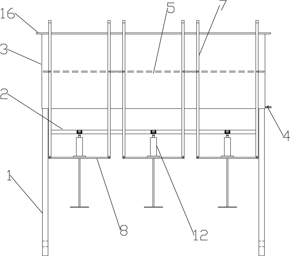
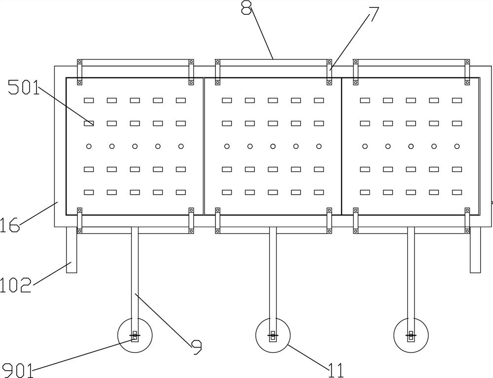
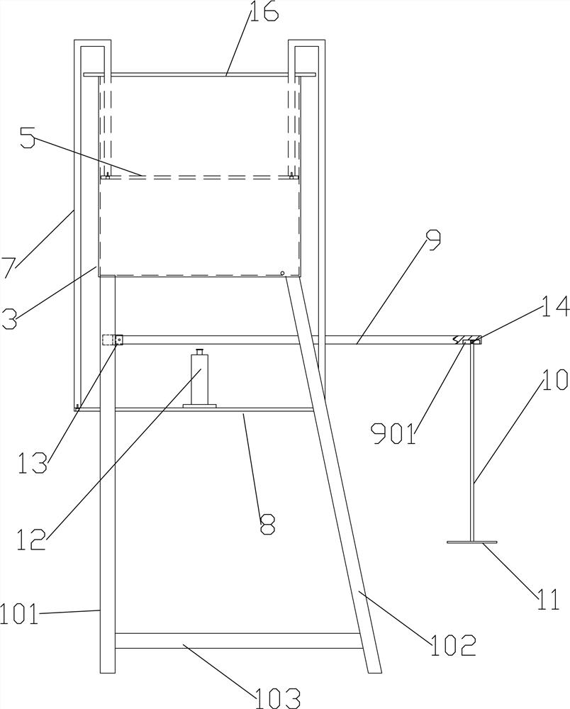
[0027] Such as Figure 1~3 As shown, an indoor foundation soil preparation device capable of maintaining the stress state on site includes a support 1. In this embodiment, the support 1 includes a vertical support leg 101 and an oblique support leg 102, and the vertical support leg 101 and the oblique support leg 102 is connected by horizontal support bar 103. The included angle between the inclined support legs 102 and the vertical direction is 20°, which reduces the occupied space as much as possible while enhancing the structural stability. A crossbeam 2 is provided on the support 1 , specifically, the crossbeam 2 is arranged between two numerical support legs 101 .
[0028] The upper end of the bracket 1 is provided with a consolidation model box 3, the aspect ratio of the consolidation model box 3 is 3:1, and the longer length is sufficient for the foundation to be prepared for multiple tests at one time. The consolidation model box 3 is provided with a drain valve 4, a...
PUM
 Abstract
Description
Claims
Application Information