
Conductor direct current resistance testing method

A DC resistance test, conductor technology, applied in the direction of measuring resistance/reactance/impedance, measuring device, measuring electrical variables, etc., can solve problems such as high temperature, and achieve the effect of ensuring accuracy and avoiding uncertainty

Pending Publication Date: 2021-08-27
上海国缆检测股份有限公司
View PDF8 Cites 0 Cited by
  • Summary
  • Abstract
  • Description
  • Claims
  • Application Information

AI Technical Summary

Problems solved by technology

The disadvantage of this method is that welding will generate high temperature. Whether the conductor has experienced high temperature will affect the measurement of conductor resistance has not yet been studied. In addition, aluminum and aluminum alloy welding requires professional and technical personnel to operate, which raises the threshold of operation.

Method used


Image

  • Conductor direct current resistance testing method
  • Conductor direct current resistance testing method

Examples


Embodiment Construction

[0030] The specific implementation manners of the present invention will be described in further detail below in conjunction with the accompanying drawings. These embodiments are only used to illustrate the present invention, not to limit the present invention.

[0031] In the description of the present invention, it should be noted that the terms "center", "longitudinal", "transverse", "upper", "lower", "front", "rear", "left", "right", " The orientations or positional relationships indicated by "vertical", "horizontal", "top", "bottom", "inner", "outer", etc. are based on the orientation or positional relationships shown in the drawings, and are only for the convenience of describing the present invention and simplifying Describes, but does not indicate or imply that the device or element referred to must have a specific orientation, be constructed in a specific orientation, and operate in a specific orientation, and therefore should not be construed as limiting the inventio...


PUM


Abstract

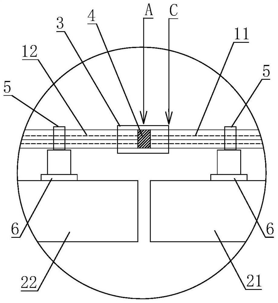
The invention relates to the technical field of conductor resistance measurement, and in particular relates to a conductor direct current resistance testing method. The method comprises the steps of cutting off a conductor at a potential pole to form a middle section and end sections positioned at two ends of the middle section, connecting the middle section and the end sections through crimping pipes of which the interiors are axially through, filling a conductive material between the middle section and the end sections in the crimping pipes, and crimping two ends of the crimping pipes with the middle section and the end sections respectively. The crimping can enable the paint films of monofilaments at the joints of the middle section and the end sections of the conductor and the crimping pipes to be broken, so that the monofilaments are in full contact, full contact of the monofilaments at the potential pole of the conductor is realized, and the crimping pipes is filled with the conductive material, so that the sections of the conductor can be in good contact, and the test current can smoothly pass through. It can be ensured that an accurate voltage value is measured at the potential pole of the conductor, and uncertainty of conductor resistance measurement caused by high welding temperature is avoided.

Description

technical field [0001] The invention relates to the technical field of conductor resistance measurement, in particular to a conductor DC resistance test method. Background technique [0002] At present, the measurement method of conductor resistance mainly refers to the national standard GB / T 3048.4-2007, which stipulates the test equipment, sample preparation, test procedures and other contents. The principle of resistance measurement of conventional conductors is to use a test bridge or other types of resistance testing instruments, use a four-terminal measuring fixture or test clamp to connect the surface of the conductor to be tested, and connect the conductor to the current terminal and voltage terminal of the resistance testing instrument. The positions are respectively used as the current electrode and potential electrode of the conductor. The resistance testing instrument outputs DC current and DC voltage. The current passes through the conductor and the resistance t...

Claims


Application Information

Patent Timeline
Patent Type & Authority Applications(China)
IPC IPC(8): G01R27/08
CPCG01R27/08
Inventor 肖敬成顾霄胡冬伟王洪昌李星辰朱涛闫笑寒申永涛贺金红张荣王子强李闯范玉军
Owner 上海国缆检测股份有限公司
Learn More