
Camera and laser composite guide dispensing compensation method and related device

A compensation method and a technology of guiding points, which are applied to the device, image analysis, and instrument for coating liquid on the surface, can solve the problems of increased cost, long debugging cycle, and high quality requirements of product materials, saving manpower and cost, guaranteeing The effect of glue road accuracy and low material requirements

Active Publication Date: 2021-08-27
SHENZHEN SHIZONG AUTOMATION EQUIP CO LTD
View PDF7 Cites 3 Cited by
  • Summary
  • Abstract
  • Description
  • Claims
  • Application Information

AI Technical Summary

Problems solved by technology

When the dispensing machine equipment produces products with high precision requirements, due to the differences in the material itself, such as deformation, etc., it will cause problems such as deviation of the glue path.
[0003] In the related technology, the relative guidance of the 2D camera or the 3D camera is used to guide the dispensing. Among them, the 2D camera can only locate the two-dimensional coordinates, and the Z direction cannot be accurately positioned.
The use of 3D cameras will cause a series of problems such as increased costs, long debugging cycles, and high quality requirements for product materials. For example, dirt on the product will have a greater impact on the 3D vision camera.

Method used


Image

  • Camera and laser composite guide dispensing compensation method and related device
  • Camera and laser composite guide dispensing compensation method and related device
  • Camera and laser composite guide dispensing compensation method and related device

Examples


Embodiment Construction

[0051] Embodiments of the present invention are described in detail below, examples of which are shown in the drawings, wherein the same or similar reference numerals designate the same or similar elements or elements having the same or similar functions throughout. The embodiments described below by referring to the figures are exemplary only for explaining the present invention and should not be construed as limiting the present invention.

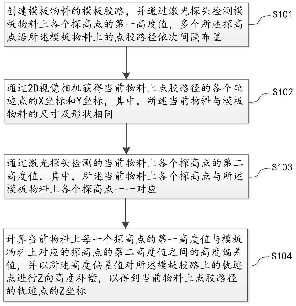
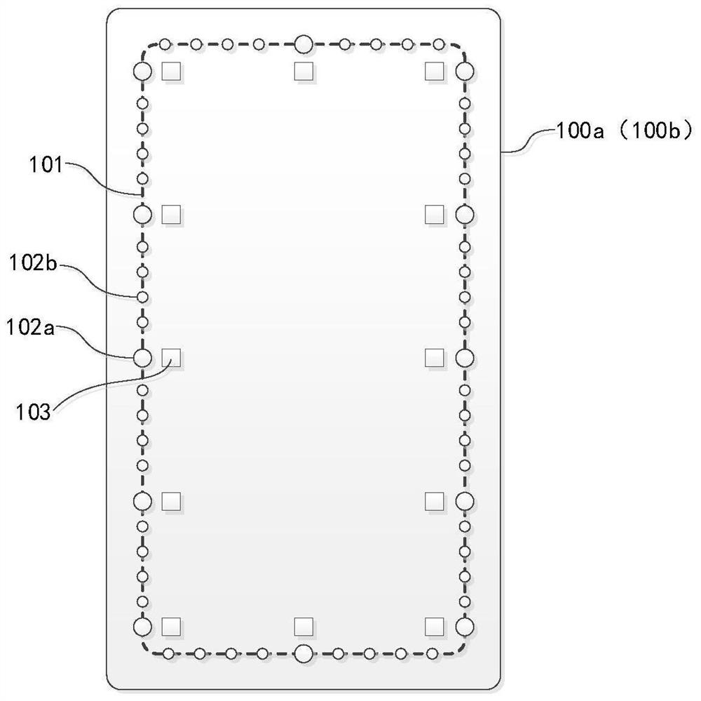
[0052] refer to figure 1 as shown, figure 1 A flow chart of an embodiment of the camera-laser compound guided dispensing compensation method provided by the embodiment of the present invention is shown. For the convenience of description, only the parts related to the embodiment of the present invention are shown. Specifically, the camera and laser compound guided dispensing compensation method can be executed by a computer device. It can be understood that the computer device can be an independent device, or can be integrated in a disp...


PUM


Abstract

The invention discloses a camera and laser composite guide dispensing compensation method and device, computer equipment and a storage medium thereof. The method comprises the steps of creating a template glue path of a template material, and detecting a first height value of each detection point on the template material through a laser probe; obtaining x coordinates and Y coordinates of all track points of a dispensing path on the current material through a 2D visual camera; detecting a second height value of each detection point on the current material through a laser probe; and calculating a height deviation value between the first height value of the high detection point on the current material and the second height value of the corresponding high detection point on the template material, and performing Z-direction height compensation on the track point on the template glue path according to the height deviation value to obtain a Z coordinate of the track point of the glue dispensing path on the current material. According to the method disclosed by the embodiment of the invention, the following change of the glue path and the material deformation is realized, the glue path accuracy is ensured, in addition, the quality effects of glue height, glue thickness and the like of dispensing are better due to height compensation, in addition, the cost is low, and the adaptability is better.

Description

technical field [0001] The present invention relates to the field of glue dispensing technology, in particular to a camera and laser compound guided glue dispensing compensation method, device, computer equipment and storage medium thereof. Background technique [0002] Glue dispensing is a process of smearing, potting, and dripping electronic glue, oil or other liquids on the product, so that the product can stick, pot, insulate, fix, and smooth the surface. When the dispensing machine equipment produces products with high precision requirements, there will be problems such as deviation of the glue path due to differences in the material itself, such as deformation and other reasons. [0003] In the related art, a 2D camera is used for relative guidance or a 3D camera is used to guide dispensing, wherein the 2D camera can only locate two-dimensional coordinates, and the Z direction cannot be accurately positioned. The use of 3D cameras will have a series of problems such a...

Claims


Application Information

Patent Timeline
Patent Type & Authority Applications(China)
IPC IPC(8): G06T7/70B05C5/00
CPCG06T7/70B05C5/00Y02P10/25
Inventor 王国辉黄爱林刘捷
Owner SHENZHEN SHIZONG AUTOMATION EQUIP CO LTD
Learn More