Flywheel energy storage device

A flywheel energy storage and flywheel technology, which is applied in the field of flywheel energy storage, can solve the problems that the safety and service life of the flywheel energy storage device cannot be guaranteed, and achieve the effect of preventing friction and protecting the motor

Active Publication Date: 2021-08-27
PINGGAO GRP +1
View PDF11 Cites 2 Cited by
  • Summary
  • Abstract
  • Description
  • Claims
  • Application Information

AI Technical Summary

Problems solved by technology

[0004] In order to achieve high power and high energy storage for the flywheel energy storage device, it is necessary to increase the axial length of the flywheel motor rotor to form a long mandrel shaft structure. When the shafting of the flywheel motor passes through the resonance zone, the large rad

Method used


Image

  • Flywheel energy storage device
  • Flywheel energy storage device

Examples


Embodiment Construction

[0032] In order to make the object, technical solution and advantages of the present invention clearer, the present invention will be further described in detail below in conjunction with the accompanying drawings and embodiments. It should be understood that the specific embodiments described here are only used to explain the present invention, and are not intended to limit the present invention, that is, the described embodiments are only some of the embodiments of the present invention, but not all of the embodiments. The components of the embodiments of the invention generally described and illustrated in the figures herein may be arranged and designed in a variety of different configurations.

[0033] Accordingly, the following detailed description of the embodiments of the invention provided in the accompanying drawings is not intended to limit the scope of the claimed invention, but merely represents selected embodiments of the invention. Based on the embodiments of the...


PUM


Abstract

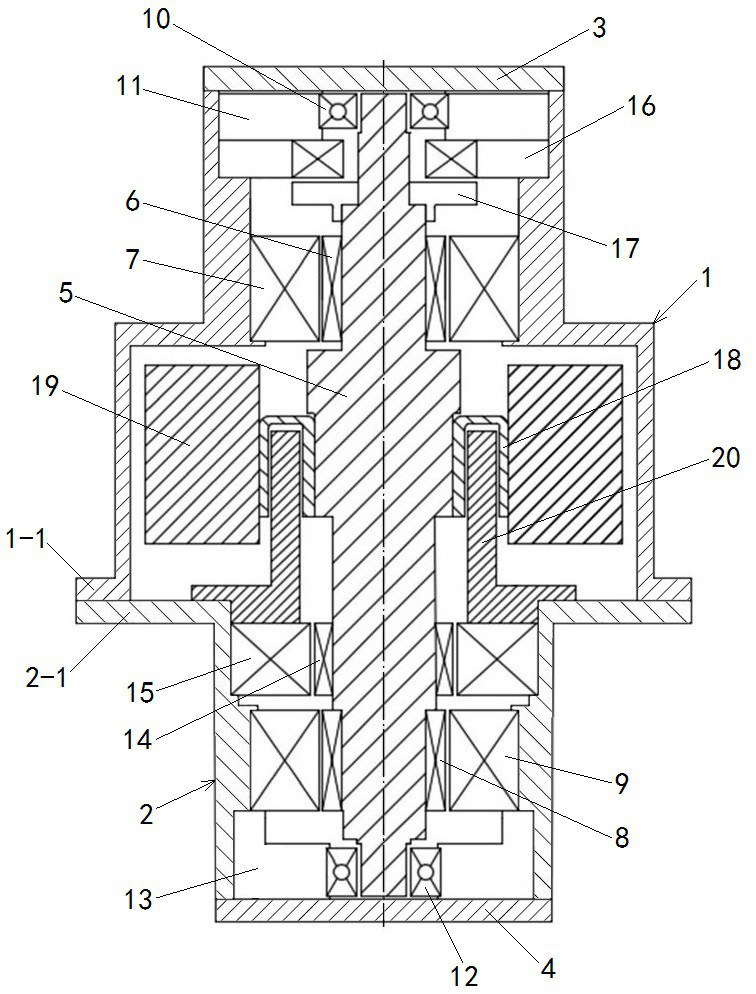
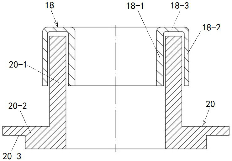
The invention provides a flywheel energy storage device. The flywheel energy storage device comprises a shell; a mandrel; a first radial electromagnetic bearing; a second radial electromagnetic bearing; a first protection bearing; a second protection bearing; a motor; a flywheel; and a friction limiting piece; wherein a radial gap between a stator and a rotor of the second radial electromagnetic bearing is b; the radial clearance between the inner ring of the second protection bearing and the mandrel is a, and a is less than b; the radial gap between the stator and the rotor of the motor is c, and c is greater than b; the motor comprises a wheel body and a hub, and an annular space is formed by the inner ring wall and the outer ring wall of the hub, the friction limiting piece comprises an extending part extending into the annular space, the radial gap between the extending part and the inner and outer ring walls is d, and d is smaller than b. By arranging the friction limiting piece, radial vibration displacement of the mandrel is forcibly limited, the motor rotor is protected against friction with the motor stator, the bearing rotor of the radial electromagnetic bearing is protected against friction with the bearing stator in cooperation with the protection bearing, and the electromagnetic bearing and the motor are better protected; and the use safety and the service life of the flywheel energy storage device are ensured.

Description

technical field [0001] The invention relates to the technical field of flywheel energy storage, in particular to a flywheel energy storage device. Background technique [0002] Flywheel energy storage refers to the energy storage method that uses the motor to drive the flywheel to rotate at high speed, and then uses the flywheel to drive the generator to generate electricity when needed. Flywheel energy storage devices usually use magnetic suspension bearings (magnetic bearings for short) to reduce friction when the motor rotor rotates. In order to protect the magnetic suspension bearings, flywheel energy storage devices usually include protective bearings. The protective bearings are when the support of the magnetic bearings does not work or due to In the case of failure for some reason, the mechanical boundary where the stator and rotor touch, this is an additional set of passive bearings, and precision angular contact ball bearings, deep groove ball bearings, etc. are usu...

Claims


Application Information

Patent Timeline
IPC IPC(8): H02K5/16H02K7/02
CPCH02K5/161H02K7/025Y02E60/16
Inventor 田刚领戴兴建徐旸张兴张剀张柳丽阮鹏白亚平崔美琨
Owner PINGGAO GRP
Why Eureka
Try Eureka