Voidable rotor support structure and aero-engine

A technology of rotor support and engine, which is applied in the directions of engine components, machines/engines, blade support components, etc., can solve the problems of stator collision, deformation of rotor 4, and large vibration amplitude of rotor 4, so as to avoid collision and meet the needs of Effects of performance and safety requirements

Active Publication Date: 2018-05-25
AECC COMML AIRCRAFT ENGINE CO LTD
View PDF3 Cites 8 Cited by
  • Summary
  • Abstract
  • Description
  • Claims
  • Application Information

AI Technical Summary

Problems solved by technology

However, after the failure of the rotor support structure, due to the loss of reliable support of the outer ring of the bearing, it may cause the rotor 4 to generate a large vibration amplitude instantaneously, resulting in serious deformation of the rotor 4 or collision with the stator, which will affect the working belt of the engine. a certain danger

Method used


Image

  • Voidable rotor support structure and aero-engine
  • Voidable rotor support structure and aero-engine
  • Voidable rotor support structure and aero-engine

Examples


Embodiment Construction

[0025] The present invention will be described in detail below. In the following paragraphs, different aspects of the embodiments are defined in more detail. The aspects so defined can be combined with any other aspect or aspects, unless it is clearly indicated that they cannot be combined. In particular, any feature considered to be preferred or advantageous may be combined with one or more other features considered to be preferred or advantageous.

[0026] The terms "first" and "second" appearing in the present invention are only for convenience of description, to distinguish different components with the same name, and do not indicate a sequence or a primary-secondary relationship.

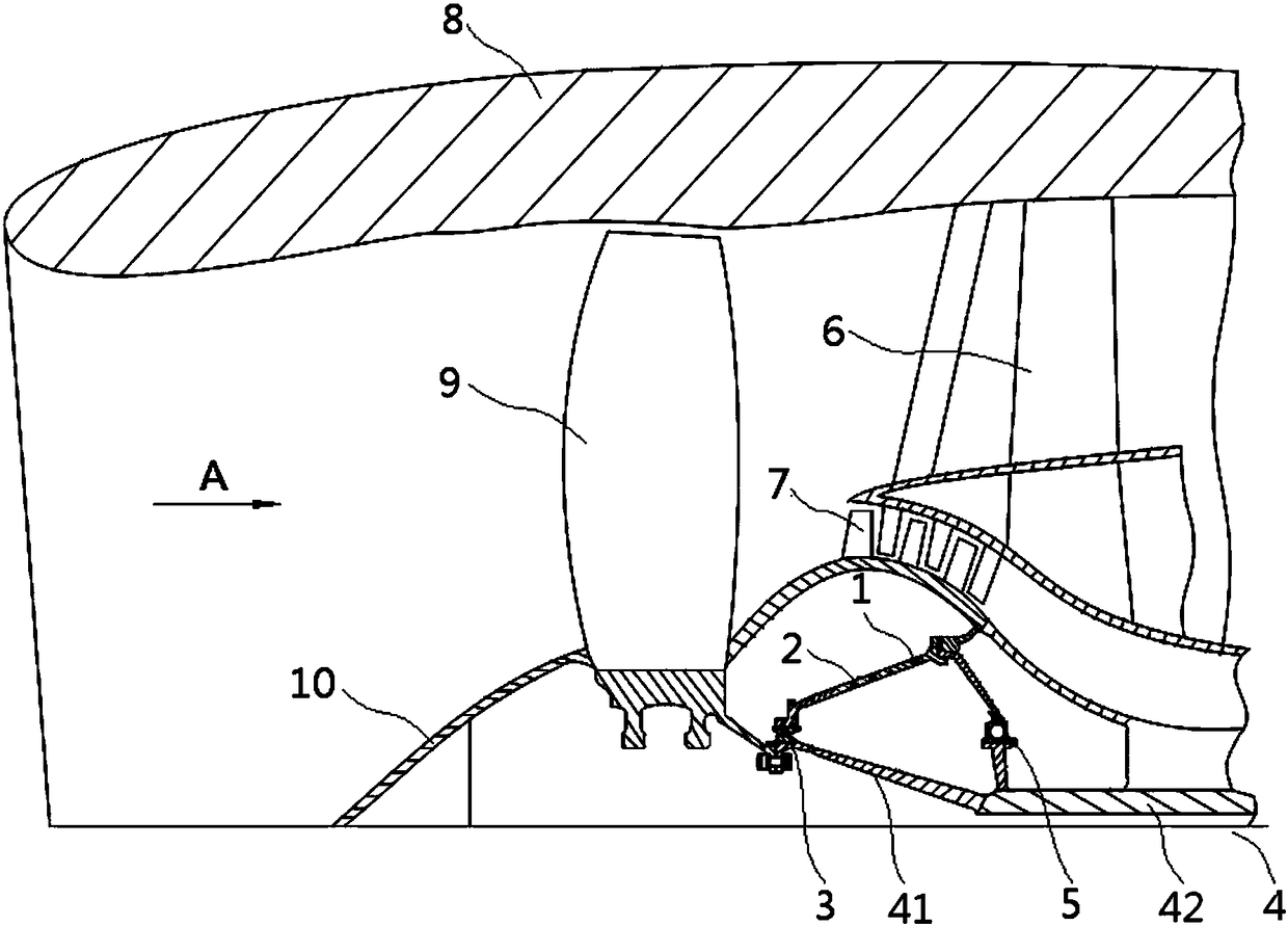
[0027] In the description of the present invention, it should be understood that the terms "front", "rear", "circumferential", "axial" and "radial" indicate the orientation or positional relationship based on the orientation shown in the drawings. The or positional relationship is only for the con...


PUM


Abstract

The invention relates to a voidable rotor support structure and an aero-engine. The voidable rotor support structure includes a support wall (1) and a portion fusing structure (2) which are arranged in the axial direction of an engine rotor (4) for supporting the rotor (4), the portion fusing structure (2) includes a connecting wall and an elastic component (23), the connecting wall can support the rotor (4) when the engine is normally operated and loses efficacy when the connecting wall is under acting force larger than a predetermined threshold value, and the elastic component is converted to support the rotor (4). According to the voidable rotor support structure, after the connecting wall loses efficacy when the engine is under the acting force larger than the predetermined threshold value, the elastic component can still support the rotor to some extent to reduce unbalanced load and vibration amplitude of a low pressure rotor, and energy can be further absorbed by generating elasticity and plastic deformation to prevent the unbalanced load and impulse load from being transmitted to subsequent bearing and intermediate cases.

Description

Technical field [0001] The invention relates to the technical field of aeroengines, in particular to a failable rotor support structure and an aeroengine. Background technique [0002] The low-pressure rotor of a typical turbofan engine generally includes a fan, a supercharging stage, a low-pressure turbine, and a rotating shaft. The low-pressure rotor is supported by multiple bearings and transmits the force and torque generated by the turbine to the supercharging stage and the fan. Under normal circumstances, the center of gravity of each component such as the fan, the supercharger stage, and the low-pressure turbine coincides with the shaft. In order to ensure the margin of critical speed, the low-pressure rotor system is generally supported by three bearings. figure 1 , The first bearing assembly 3 and the second bearing assembly 5 are located near the fan rotor and are called fan bearings. The fan bearing connects the fan rotor to the stator intermediate casing 6 through th...

Claims


Application Information

Patent Timeline
Patent Type & Authority Applications(China)
IPC IPC(8): F01D25/28F01D5/02
CPCF01D5/02F01D25/28
Inventor 柴象海宋会英王少辉侯亮史同承
Owner AECC COMML AIRCRAFT ENGINE CO LTD
Why Eureka
Try Eureka