
Farmland residual crop straw treatment equipment

A technology of crop straw and processing equipment, which is applied in the field of agricultural equipment and can solve the problems of large safety and hidden dangers of hanging baskets

Inactive Publication Date: 2021-08-31
安徽永民种业有限责任公司
View PDF14 Cites 0 Cited by
  • Summary
  • Abstract
  • Description
  • Claims
  • Application Information

AI Technical Summary

Problems solved by technology

[0004] The purpose of the present invention is to solve the problem of large safety hazards in the use of the hanging basket in the prior art, and propose a kind of farmland residual crop straw processing equipment

Method used


Image

  • Farmland residual crop straw treatment equipment
  • Farmland residual crop straw treatment equipment
  • Farmland residual crop straw treatment equipment

Examples


Embodiment 1

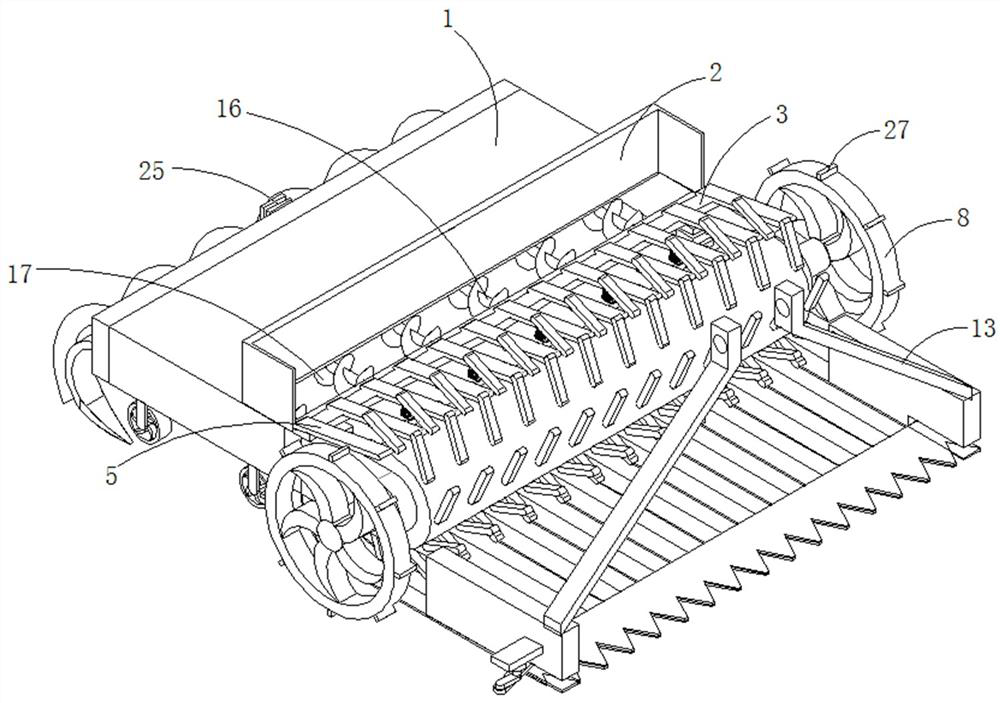
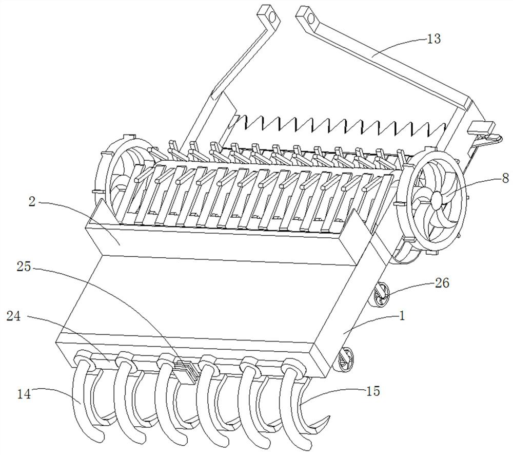
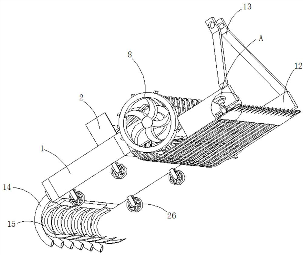
[0038] refer to Figure 1-6, a kind of equipment for processing residual crop straw in farmland, comprising a crushing box 1, a feeding port is opened on the top of the crushing box 1, a U-shaped feeding hopper 2 is arranged at the outlet of the feeding port, and a U-shaped feeding hopper 2 is arranged at the opening of the U-shaped feeding hopper 2 The triangular positioning plate 3 is fixedly connected with the first vibrating motor 4 on the outer wall of the crushing box 1, and the vibrating end of the first vibrating motor 4 is fixedly connected with the triangular positioning plate 3, and the inclined surface of the triangular positioning plate 3 is fixed with evenly distributed The material guide rod 5 and the outer wall of the pulverizing box 1 near the U-shaped feed hopper 2 are fixedly connected with symmetrically distributed connecting plates 6, and the rotating shaft 7 is connected between the connecting plates 6, and the end of the rotating shaft 7 passes through th...

Embodiment 2

[0048] refer to Figure 1-6 , a kind of equipment for processing residual crop straw in farmland, comprising a crushing box 1, a feeding port is opened on the top of the crushing box 1, a U-shaped feeding hopper 2 is arranged at the outlet of the feeding port, and a U-shaped feeding hopper 2 is arranged at the opening of the U-shaped feeding hopper 2 The triangular positioning plate 3 is fixedly connected with the first vibrating motor 4 on the outer wall of the crushing box 1, and the vibrating end of the first vibrating motor 4 is fixedly connected with the triangular positioning plate 3, and the inclined surface of the triangular positioning plate 3 is fixed with evenly distributed The material guide rod 5 and the outer wall of the pulverizing box 1 near the U-shaped feed hopper 2 are fixedly connected with symmetrically distributed connecting plates 6, and the rotating shaft 7 is connected between the connecting plates 6, and the end of the rotating shaft 7 passes through t...


PUM


Abstract

The invention discloses farmland residual crop straw treatment equipment and a use method thereof, and belongs to the technical field of agricultural instruments. The farmland residual crop straw treatment equipment comprises a smashing box, a feeding port is formed in the top of the smashing box, a U-shaped feeding hopper is arranged at the feeding port, a triangular positioning plate is arranged at an opening of the U-shaped feeding hopper, a first vibration motor is fixedly connected to the outer side wall of the smashing box, and the vibration end of the first vibration motor is fixedly connected with the triangular positioning plate. Uniformly distributed guide rods are fixedly connected to the inclined surface of the triangular positioning plate, symmetrically distributed connecting plates are fixedly connected to the outer wall of the side, close to the U-shaped feeding hopper, of the smashing box, a rotating shaft is rotatably connected between the connecting plates, the end of the rotating shaft penetrates through the connecting plates and extends outwards, and a rotating wheel is fixedly connected to the extending end of the rotating shaft. A roller is fixedly connected to the outer side wall of the rotating shaft between the connecting plates. According to the farmland residual crop straw treatment equipment, the functions of straw collection, secondary smashing and field returning are achieved, smashing is thorough, and the field returning effect is ideal.

Description

technical field [0001] The invention relates to the technical field of agricultural equipment, in particular to equipment for treating residual crop stalks in farmland. Background technique [0002] Straw returning to the field can increase soil organic matter, improve soil structure, loosen the soil, increase porosity, reduce capacity, and promote microbial activity and the growth of crop roots. However, if the method is improper, it will also lead to the increase of soil pathogens, the aggravation of crop diseases and the lack of seedlings (stiff seedlings) and other undesirable phenomena. Therefore, only by taking reasonable measures to return straw to the field can a good effect be achieved. For many years, the remaining straw after harvesting corn and other crops has been burned in large quantities, which has caused great pollution to the natural environment. On the other hand, due to the perennial pursuit of food High yield, continuous increase of crop density, thus p...

Claims


Application Information

Patent Timeline
IPC IPC(8): A01D34/835
CPCA01D34/8355
Inventor 赵德军赵德民赵鹏赵雷陈令志陈振东戚化学赵宏周维军王化龙
Owner 安徽永民种业有限责任公司
Learn More