Snake bone linkage structure

A technology of snake bone and rotating structure, which is applied in pivot connection, medical science, endoscope, etc. It can solve the problems of laborious operation, low flexibility of snake bone tube, and small range of motion, so as to reduce production cost and improve The effect of product consistency and large range of activities

Pending Publication Date: 2021-08-31
ENOVE PRECISION PLASTICS CATHETER
View PDF1 Cites 1 Cited by
  • Summary
  • Abstract
  • Description
  • Claims
  • Application Information

AI Technical Summary

Problems solved by technology

Two adjacent serpentine tube unit sections can swing through the rotation pair composed of the first connecting structure and the second connecting structure, and there is no need to realize the joint positioning by riveting like the traditional snake tube, but the snake tube is moving The flexibility is not high, the range of activities is small, and the operation is laborious

Method used


Image

  • Snake bone linkage structure
  • Snake bone linkage structure
  • Snake bone linkage structure

Examples


Embodiment 1

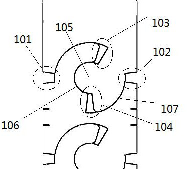
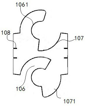
[0032] refer to Figure 1-Figure 5 , a snake bone link structure, the snake bone link structure is integrally formed by laser cutting a metal tube, the link structure includes a patterned rotating structure 1, and the patterned rotating structure 1 includes a primary rotating part and is compatible with the primary rotating part The second-stage rotating part is provided, the first-stage rotating part includes a first-stage arc-shaped slide block 1061 and the second-stage arc-shaped slideway 107, the second-stage rotating part includes a first-stage arc-shaped slideway 106 and a second-stage arc-shaped slide block 1071, and one The first-level arc slide block 1061 is compatible with the first-level arc slideway 106, the second-level arc slide block 1071 is compatible with the second-level arc slideway 107, the first-level arc slide block 1061, the second-level arc slideway Road 107, primary arc slideway 106 and secondary arc slide block 1071 are concentric arcs;

[0033] When...

Embodiment 2

[0036] Others are consistent with the scheme of Embodiment 1. The link structure of the snake bone is a two-way snake bone link structure, and the link structure includes patterned rotating structures 1 symmetrically distributed on the metal circular tube.

Embodiment 3

[0038] The rest are consistent with the scheme of embodiment 1 or 2. The metal round pipe includes a metal pipe and a front connecting pipe and a rear connecting pipe arranged at both ends of the metal pipe. The length of the front connecting pipe is shorter than the length of the rear connecting pipe. Ensure that the joint section at the front end of the metal tube is relatively short, and the joint section at the rear end is relatively long, so as to ensure that the front end moves first when the overall snake bone bends, so that it is more flexible and labor-saving.


PUM


Abstract

The invention discloses a snake bone linkage structure. The snake bone linkage structure is integrally formed through laser cutting of a metal round pipe, the linkage structure comprises pattern rotating structures, each pattern rotating structure comprises a first-stage rotating part and a second-stage rotating part matched with the first-stage rotating part, wherein the first-stage rotating part comprises a first-stage arc-shaped sliding block and a second-stage arc-shaped sliding way, the second-stage rotating part comprises a first-stage arc-shaped sliding way and a second-stage arc-shaped sliding block, the first-stage arc-shaped sliding block is matched with the first-stage arc-shaped sliding way, the second-stage arc-shaped sliding block is matched with the second-stage arc-shaped sliding way, and the first-stage arc-shaped sliding block, the second-stage arc-shaped sliding way, the first-stage arc-shaped sliding way and the second-stage arc-shaped sliding block are concentric arcs. The snake bone linkage structure is integrally formed in a laser cutting mode, the problem that existing snake bones can only be achieved through riveting is solved, the snake bones are easy to machine, and the product consistency is improved.

Description

technical field [0001] The invention relates to the technical field of medical devices, in particular to a link structure of snake bones. Background technique [0002] At present, with the mature application of laser processing, the original riveted snake bone joint has been gradually eliminated due to its high processing cost, and snake bone joints formed integrally by laser cutting have appeared on the market. Laser cutting snake bone has become a new way to replace riveted snake bone joint due to its low processing cost, convenient processing and easy proofing. Publication No. CN212972894U relates to a snake bone tube unit section and a snake bone tube. The snake bone tube unit section includes a cylinder body. The cylinder body has a front end and a rear end. The front end is provided with a first connection structure. The first connection structure includes a pair of The connecting ear is symmetrically arranged on the body axis. The connecting ear includes an annular b...

Claims


Application Information

Patent Timeline
Patent Type & Authority Applications(China)
IPC IPC(8): A61B1/008A61B1/005F16C11/04
CPCA61B1/0055A61B1/0057A61B1/008F16C11/04
Inventor 秦晓鹏魏先锋
Owner ENOVE PRECISION PLASTICS CATHETER
Why Eureka
Try Eureka