
Clinical drainage equipment for emergency intensive care unit

An intensive care unit, clinical technology, applied in hospital equipment, beds, suction equipment, etc., can solve the problem of consuming family members' energy and other problems, achieve the effect of saving energy, not easy to bend and come out, and improve efficiency and safety

Inactive Publication Date: 2021-08-31
程艳艳
View PDF0 Cites 0 Cited by
  • Summary
  • Abstract
  • Description
  • Claims
  • Application Information

AI Technical Summary

Problems solved by technology

[0003] Most of the drainage devices currently used in clinical practice are drainage tubes. The drainage tubes are placed on the parts of the patient that need drainage, and the other end is connected to a drainage bottle or a drainage bag. Since the drainage tubes are mostly soft tubular structures, they need to be used when using them. Always pay attention to observation to avoid the drainage tube being affected by pressure and twisting, and pay attention to the fixation of the drainage tube to avoid displacement and prolapse. Sometimes the drainage tube needs to be clamped or opened as required, which consumes a lot of energy for the family members
[0004] When the existing drainage equipment is used, it is necessary to pay attention to the fixation and state of the drainage tube at all times to avoid its bending and detachment, which will affect the drainage, and the family members need to manually switch the drainage, which consumes a lot of energy for the family members. Therefore, we propose an emergency intensive care Drainage equipment for clinical use

Method used


Image

  • Clinical drainage equipment for emergency intensive care unit
  • Clinical drainage equipment for emergency intensive care unit
  • Clinical drainage equipment for emergency intensive care unit

Examples


Embodiment Construction

[0024] In order to make the technical means, creative features, achievement goals and effects realized by the present invention easy to understand, the present invention will be further described below with reference to the specific embodiments.

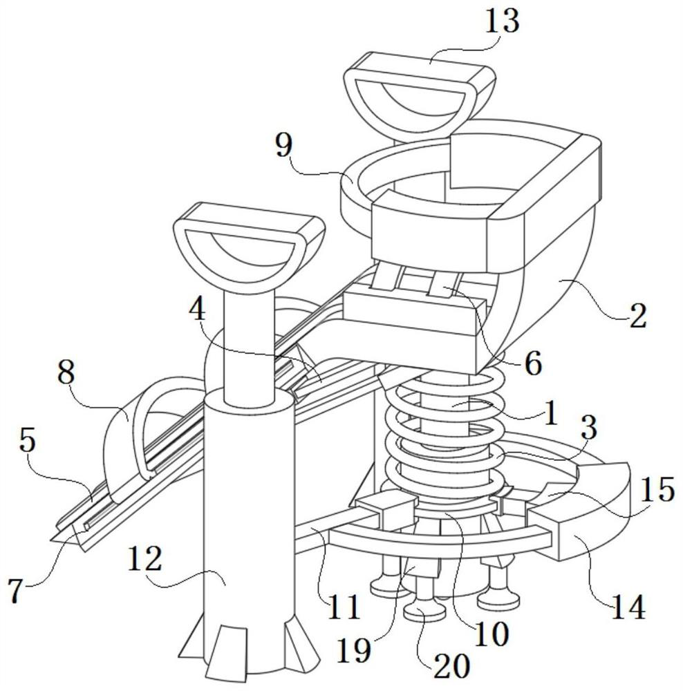
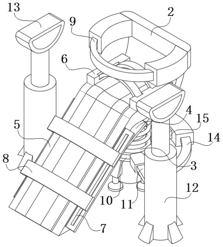
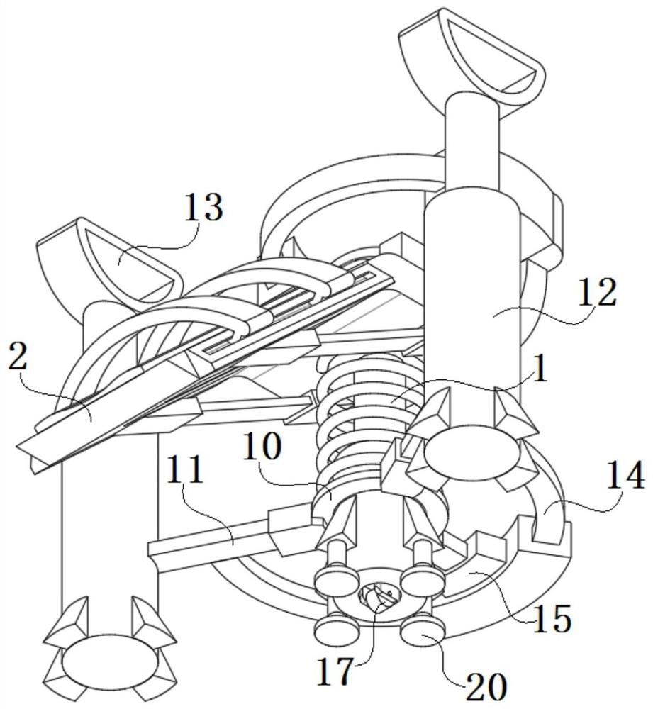
[0025] Please refer to figure 1 As shown in 6, the present invention is a drainage device for clinical use in an emergency intensive care unit, a drainage device for clinical use in an emergency intensive care unit, comprising a telescopic drainage tube 1, and a drainage mechanism and an auxiliary mechanism arranged on the telescopic drainage tube 1 The drainage mechanism is arranged above the auxiliary mechanism; the telescopic drainage tube 1 is well fixed on the patient through the fixing assembly, and does not affect the movement of the patient, and the telescopic drainage tube 1 is not easy to bend and come out, which improves the drainage efficiency and safety. The monitoring and automatic interception of drainage fluid are rea...


PUM


Abstract

The invention discloses clinical drainage equipment for an emergency intensive care unit. The clinical drainage equipment comprises a telescopic drainage tube, a drainage mechanism and an auxiliary mechanism, wherein the drainage mechanism and the auxiliary mechanism are arranged on the telescopic drainage tube; the drainage mechanism is arranged above the auxiliary mechanism; the drainage mechanism comprises a flow guide connecting sealing plug, a drainage bag, a fixing assembly and a flow intercepting assembly, and the fixing assembly and the flow intercepting assembly are arranged on the telescopic drainage tube; the fixing assembly comprises a six-edge clamping ring, a self-locking clamp, a pressing toggle clip and a bent fixing claw; and the flow intercepting assembly comprises a flow sensor, an information transmission column, a processing microcomputer, a linear guide rail, a sliding push rod, an embedded clamping plate, a concentric-square-shaped telescopic traction frame and a flow intercepting clamping plate. The telescopic drainage tube is well fixed to the body of a patient through the fixing assembly, movement of the patient is not affected, meanwhile, the telescopic drainage tube is not prone to being bent and disengaged, drainage safety is improved, drainage liquid is monitored and automatically cut off through the flow intercepting assembly, the energy of family members of the patient is saved, and the fixing of the device and the display of monitoring data are realized through the auxiliary mechanism.

Description

technical field [0001] The invention relates to the technical field of medical equipment, in particular to a clinical drainage device for an emergency intensive care unit. Background technique [0002] Surgical drainage guides the pus, blood, and fluid accumulated between human tissues or body cavities to the body to prevent postoperative infection and affect wound healing. In order to prevent wound infection, the drainage gauze placed in the patient's wound cavity should be replaced every day, and strict It is difficult to replace the drainage tube placed in the patient's body, and it is generally kept for several days according to the treatment needs. [0003] At present, most of the drainage devices used in clinical practice are drainage tubes. The drainage tubes are placed at the part of the patient that needs drainage, and the other end is connected to a drainage bottle or drainage bag. Because the drainage tubes are mostly soft tubular structures, when using them, it i...

Claims


Application Information

Patent Timeline
Patent Type & Authority Applications(China)
IPC IPC(8): A61M1/00A61M25/02A61G7/05
CPCA61G7/0503A61M25/02A61M2025/0253A61M2025/028A61M2205/3331A61M2205/50
Inventor 程艳艳
Owner 程艳艳
Learn More