Segmented milling positioning device and positioning method for blade of welded pipe edge milling machine
A technology of positioning device and edge milling machine, applied in the field of edge milling machine edge milling, can solve the problems of inability to widely apply to large factories, waste of steel costs, manual operation, etc.
- Summary
- Abstract
- Description
- Claims
- Application Information
AI Technical Summary
Problems solved by technology
Method used
Image
Examples
Embodiment 1
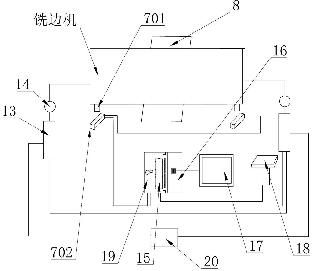
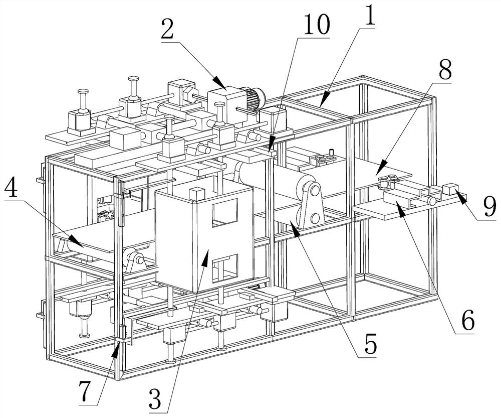
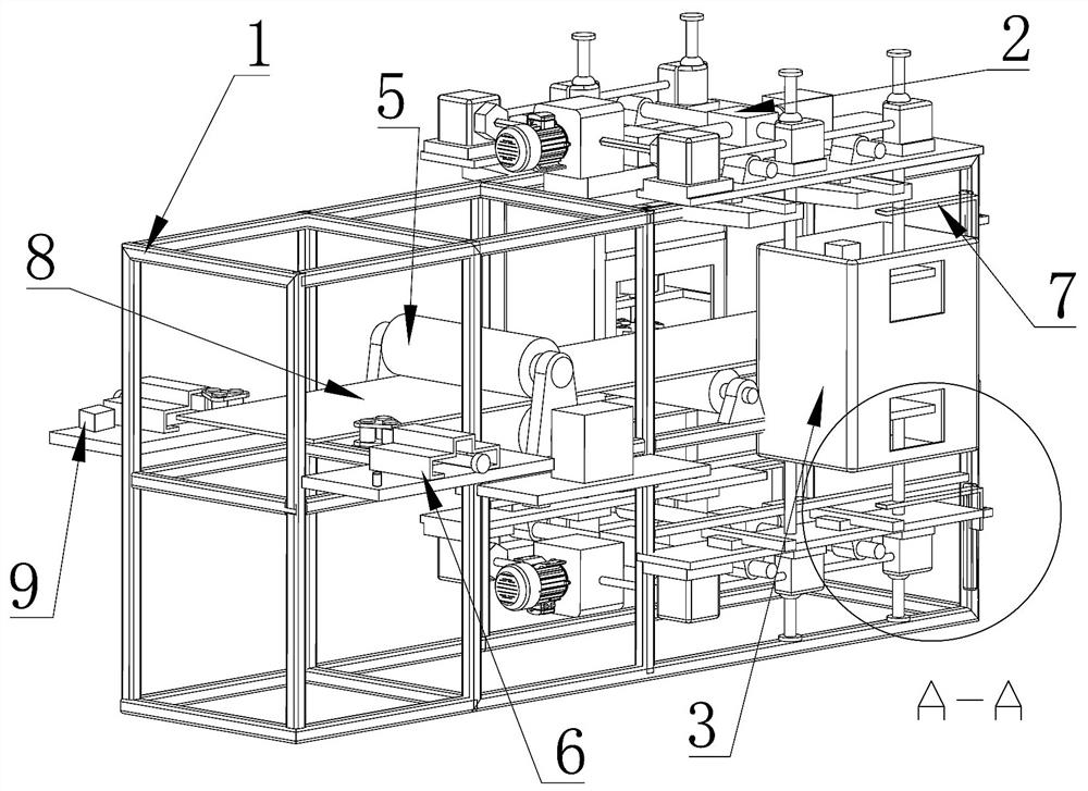
[0047] like Figure 1~13 Among them, the segmental milling positioning device of the welded pipe edge milling machine blade includes a frame 1, and a plurality of rotatable cutter heads 301 are arranged on both sides of the frame 1;
[0048] Both sides of the frame 1 are equipped with a transmission device 2, the transmission device 2 can drive the cutter head 301 to move horizontally and vertically, the horizontal direction movement is the cutting feed of the cutter head 301, and the vertical direction movement is the cutting feed or Retraction direction;
[0049] The two cutterheads 301 on the same side of the frame 1 are driven by a separate third motor 304, and the two cutterheads 301 on the same side can be used independently or alternately, so that the milling cutter device does not stop, and the two cutterheads on the same side 301 can be spliced up and down to form a cutterhead. With this structure, for most of the thinner steel plates milled by high-frequency weld...
Embodiment 2
[0062] The segmented milling positioning device and its positioning method for welded pipe edge milling machine blades include the following steps: Preliminary preparation of the milling cutter: the third motor 304 power outlet cable is connected to the frequency converter 13 after 143 laps around the magnetic ring, and the pulse on the side of the frame 1 The output communication port of the sensing body 701 is connected to the input communication port of the pulse sensing body 701 on the other side of the rack 1 with a Profibus-DP communication line, and the output communication port of the pulse sensing body 701 on one side is connected to the Profibus-DP communication line. The DP communication line is connected to the DP input port of CPU 1, the DP output port of CPU1 is connected to the input communication port of the frequency converter 13 with the Profibus-DP communication line, and the output communication port of the frequency converter 13 is connected to the frequency...
PUM
 Abstract
Description
Claims
Application Information
 - R&D
- Intellectual Property
- Life Sciences
- Materials
- Tech Scout
- Unparalleled Data Quality
- Higher Quality Content
- 60% Fewer Hallucinations
Browse by: Latest US Patents, China's latest patents, Technical Efficacy Thesaurus, Application Domain, Technology Topic, Popular Technical Reports.
© 2025 PatSnap. All rights reserved.Legal|Privacy policy|Modern Slavery Act Transparency Statement|Sitemap|About US| Contact US: help@patsnap.com


