Visual positioning method and system and computing equipment

A technology of visual positioning and computing equipment, which is applied in the direction of welding accessories, etc.

Inactive Publication Date: 2021-08-31
HUNAN UNIV
View PDF9 Cites 1 Cited by
  • Summary
  • Abstract
  • Description
  • Claims
  • Application Information

AI Technical Summary

Problems solved by technology

[0006] To this end, the present invention provides a visual positioning method, visual positioning system and computing equipment, to solve or at least alleviate the above problems

Method used


Image

  • Visual positioning method and system and computing equipment
  • Visual positioning method and system and computing equipment
  • Visual positioning method and system and computing equipment

Examples


Embodiment Construction

[0036] Exemplary embodiments of the present disclosure will be described in more detail below with reference to the accompanying drawings. Although exemplary embodiments of the present disclosure are shown in the drawings, it should be understood that the present disclosure may be embodied in various forms and should not be limited by the embodiments set forth herein. Rather, these embodiments are provided for more thorough understanding of the present disclosure and to fully convey the scope of the present disclosure to those skilled in the art.

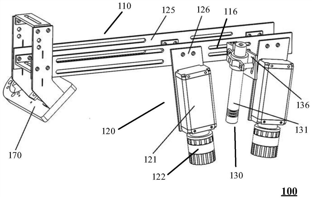
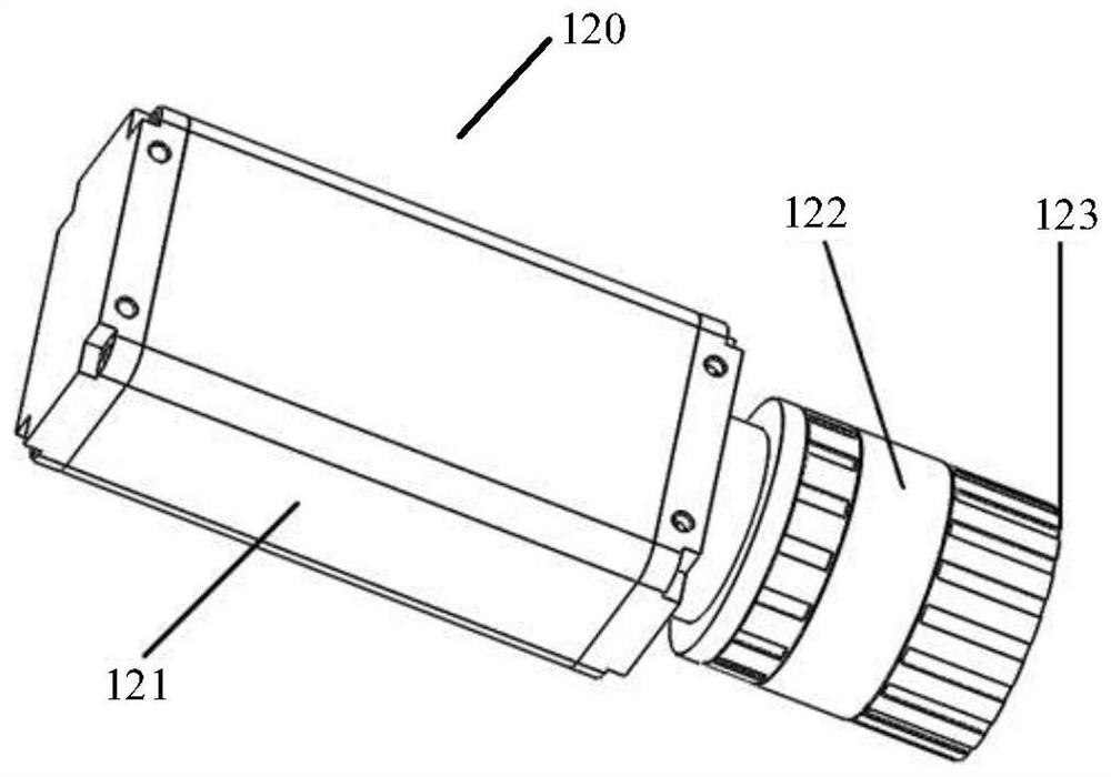
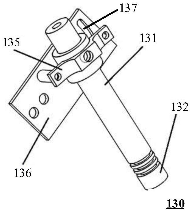
[0037]As mentioned above, the vision positioning solutions for intelligent welding or automatic welding in the prior art have more or less certain defects. Therefore, the present invention proposes a vision positioning system 100 with more optimized performance. The visual positioning system 100 can be applied to intelligent welding equipment, automatic welding equipment, etc., and is suitable for collecting weld seam images on the ...


PUM


Abstract

The invention discloses a visual positioning method, which is executed in computing equipment and comprises the following steps of: acquiring a welding seam image on the surface of a workpiece; determining welding seam feature points and image coordinates thereof on the welding seam image based on the welding seam extraction template; and determining world coordinates of the weld joint feature points based on the image coordinates, wherein the workpiece is welded based on the world coordinates of the weld joint feature points. The invention also discloses a visual positioning system, a visual positioning method executed in the system and computing equipment. According to the visual positioning method, accurate positioning of the fillet weld coordinates can be achieved, so that the efficiency of weld extraction and weld positioning is improved.

Description

technical field [0001] The invention relates to the technical field of intelligent welding, in particular to a visual positioning method, system and computing equipment. Background technique [0002] At present, most of the workpiece welding is through manual welding. Manual welding not only has low efficiency and limited production capacity, but also has uneven welding quality and unsightly finished products. Therefore, in the fields of ships, aerospace, construction machinery and rail transit, the use of welding robots to realize intelligent welding is of great significance for improving welding quality and welding efficiency. [0003] When using a welding robot for intelligent welding, the core issue is how to efficiently and accurately locate the coordinates of the weld. Traditionally, the robot teaching method is used for welding seam positioning. In this method, the robot can only weld according to the preset trajectory. Therefore, when the workpiece size and positio...

Claims


Application Information

Patent Timeline
Patent Type & Authority Applications(China)
IPC IPC(8): B23K9/32
CPCB23K9/32
Inventor 刘坚陈圣峰陈兵苏重阳
Owner HUNAN UNIV
Why Eureka
Try Eureka