
Guide wheel variable stiffness design method and variable stiffness guide wheel

A design method and variable stiffness technology, which are applied in the direction of wheels, wheels characterized by track running parts, transportation and packaging, etc., can solve the problems of large space for guide wheels and high cost of guide devices, achieve low cost, avoid potential safety hazards, small space effect

Inactive Publication Date: 2021-08-31
ZHUZHOU TIMES NEW MATERIALS TECH
View PDF7 Cites 0 Cited by
  • Summary
  • Abstract
  • Description
  • Claims
  • Application Information

AI Technical Summary

Problems solved by technology

[0010] None of the above patents involves the technical solution of adopting variable stiffness guide wheels, which cannot solve the problems of relatively large space required for guide wheel installation or high cost of guide devices

Method used


Image

  • Guide wheel variable stiffness design method and variable stiffness guide wheel
  • Guide wheel variable stiffness design method and variable stiffness guide wheel
  • Guide wheel variable stiffness design method and variable stiffness guide wheel

Examples


Embodiment Construction

[0030] Below by specific embodiment and in conjunction with accompanying drawing, the present invention will be further described:

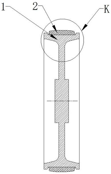
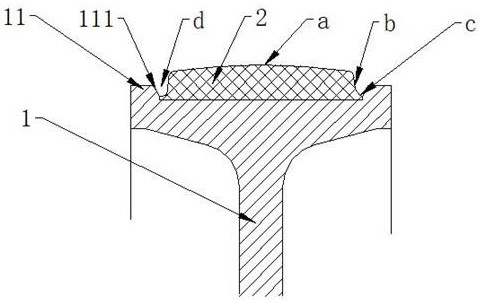
[0031] Guide wheels such as Figures 1 to 2As shown: including the hub 1 and the elastic layer 2, the two sides of the hub 1 are provided with flanges 11, and the flanges 11 on both sides are combined with the outer ring of the hub 1 to form a circular groove. The opposite side of the flanges 11 on both sides is the flange inner surface 111, and the flange inner surface 111 is a slope, so that the width of the opening of the groove is greater than the width of the bottom of the groove, so that the cross section of the groove is an inverted trapezoid.

[0032] The elastic layer 2 is embedded in the groove of the outer ring of the hub 1 by using elastic materials such as rubber and plastic, and rubber is used in this embodiment. The inner ring of the elastic layer 2 is fixedly connected with the outer ring of the hub 1 by means of vulcanization or...


PUM


Abstract

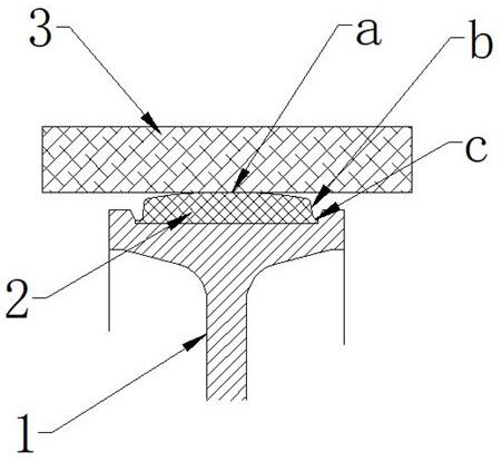
The invention relates to a guide wheel variable stiffness design method and a variable stiffness guide wheel, a point-to-surface contact mode is formed between an elastic layer and a guide rail by adjusting the shape of the free molded surface of the elastic layer of the guide wheel so that the initial stiffness is small when the elastic layer is just contacted with the guide rail, and then is gradually increased, and the guide wheel has a variable stiffness characteristic. The flanges are arranged on the two sides of the hub to form the grooves, and the elastic layers are embedded into the grooves so that rigidity inflection points are formed after the grooves are filled with the elastic layers, the rigidity is further improved, and radial deformation is controlled. Meanwhile, the flange also plays a role of hard backstop so as to control the maximum radial deformation of the elastic layer and prevent the vehicle body from deviating from the normal operation position. In addition, the flanges can guarantee that the elastic layer does not fall off even if degumming, and potential safety hazards caused by degumming are avoided. The variable stiffness guide wheel is small in required space, low in cost and easy and convenient to install and maintain.

Description

technical field [0001] The invention belongs to the technical field of rail vehicle wheels, and in particular relates to a design method for variable stiffness of a guide wheel and a variable stiffness guide wheel. Background technique [0002] With the three-dimensional development of rail transit, vehicles such as straddle monorail, empty rail car, and magnetic levitation are more and more widely used. At present, during the operation of maglev trains and some monorail vehicles, they all rely on guide wheels for turning guidance and controlling the gap between the car body and the track. [0003] In order to ensure the smooth operation of the vehicle, usually the outer ring of the guide wheel is provided with a rubber damping layer. However, the existing guide wheel rubber damping layer is cylindrical, the stiffness is linear, and the deformation of the rubber damping layer is proportional to the force. When the guide wheel comes into contact with the track, in order to ...

Claims


Application Information

Patent Timeline
Patent Type & Authority Applications(China)
IPC IPC(8): B60B17/00
CPCB60B17/00B60B17/0027B60B2900/112B60B2900/115
Inventor 颜瑶肖祥龙胡伟辉罗斌庄征宇陈刚
Owner ZHUZHOU TIMES NEW MATERIALS TECH
Learn More