Continuous weighing system for small products and weighing method thereof

A weighing system and product technology, which is applied in the fields of chemicals and manufacturing, pharmaceuticals, and food, can solve the problems of inaccurate weighing results, inaccurate weighing results, inconsistent front and rear positions, etc., to reduce damage or leakage Reduce the risk of dust, shorten the weighing cycle, and ensure the accuracy of the effect

Pending Publication Date: 2021-08-31
SHANGHAI QUNTIN-TECH CO LTD
View PDF0 Cites 3 Cited by
  • Summary
  • Abstract
  • Description
  • Claims
  • Application Information

AI Technical Summary

Problems solved by technology

If the rotation speed of the transfer plate exceeds the sliding speed of the capsule, the rear teeth on the transfer plate will directly push the rear end of the capsule along the guide passage into the weighing platform, and the capsule will be weighed during the process of being pushed by the rear teeth on the transfer plate, and the weighing result is often inaccurate ; If the rotation speed of the transfer plate is lower than a certain value, the capsule will slow down or even stop when the inertial force of the capsule is less than the frictional resistance when...

Method used


Image

  • Continuous weighing system for small products and weighing method thereof
  • Continuous weighing system for small products and weighing method thereof
  • Continuous weighing system for small products and weighing method thereof

Examples


Embodiment 1

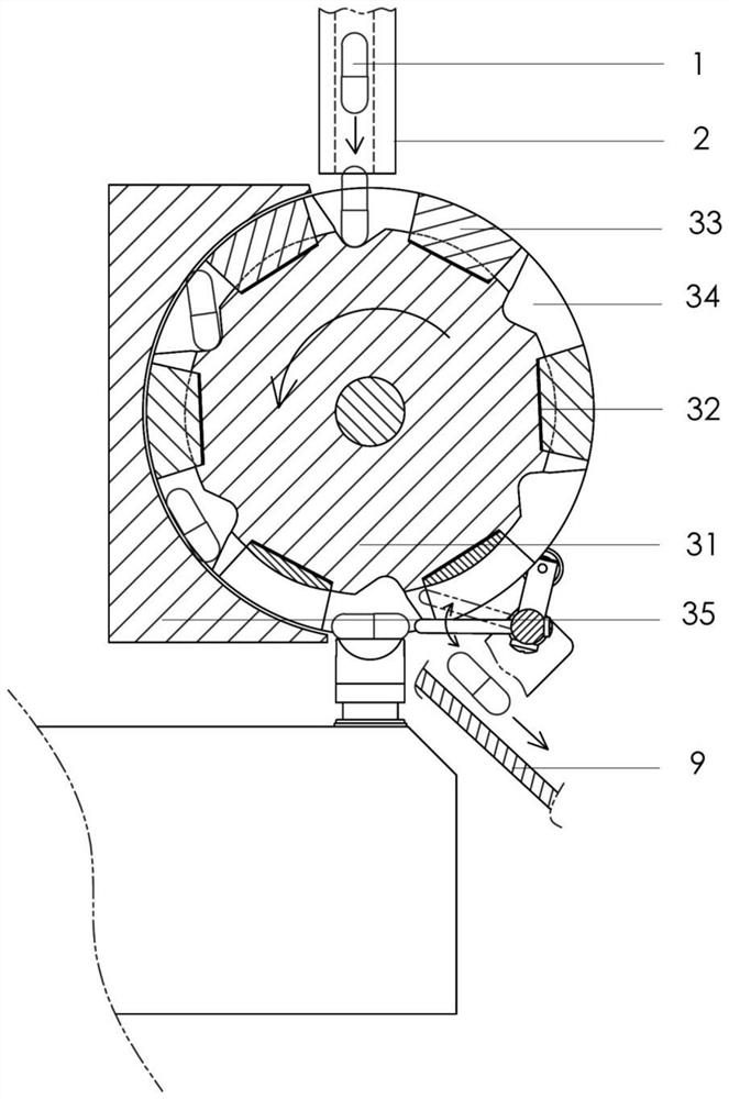
[0072] This embodiment provides a preferred implementation, based on the above structure, such as Figure 3 to Figure 5As shown, in this embodiment, several sliding blocks 33 axially reciprocate in the first channel 32 . The reset mechanism can adopt any mechanical structure that can realize the reset of the push rod 4 in the extreme position to the initial position. Preferably, the reset mechanism can use an elastic element, the elastic element is arranged on the side wall of the first channel 32 away from the push rod 4, and the push rod 4 in the extreme position is reset to the initial position through the elasticity of the elastic element; preferably, the reset The mechanism can adopt a mechanical structure combining elastic elements and guide rails. The guide rails are installed axially along the first passage 32. The slider 33 in the first passage 32 slides along the guide rails. Install elastic elements on the guide rails. The elasticity of the elastic elements will be ...

Embodiment 2

[0088] This embodiment provides a preferred implementation, based on the above structure, such as Figure 6 to Figure 8 As shown, in the present embodiment, on the end face of the same side of the transfer wheel 31 and the push rod 4, several slideways 8 are opened along the circumference of the end face toward the center of the end face; 8 reciprocating movement. The reset mechanism can adopt any mechanical structure that can reset the push rod 4 in the extreme position to the initial position. Preferably, the reset mechanism can use an elastic element, the elastic element is arranged at the bottom of the first passage 32, and contacts with the slider 33 in the first passage 32, and the push rod 4 in the extreme position is reset to the initial state through the elasticity of the elastic element Location. like Figure 8 As shown, the second cam 53 is in the shape of a semi-arc as a whole, the opening of the second cam 53 faces upwards, and the opening surface of the second...


PUM


Abstract

The invention belongs to the technical field of pharmacy, food, chemicals and processing and manufacturing, and particularly relates to a continuous weighing system for small products and a weighing method thereof. The weighing system is installed on a support; and the support is used for supporting the weighing system. The weighing system comprises a discharging mechanism, a conveying and transferring mechanism, a push rod, a pushing mechanism, a reset mechanism, a weighing mechanism and a connecting rod following mechanism. The discharging mechanism is arranged at the top of the support; the conveying and transferring mechanism is arranged below the discharging mechanism; the conveying and transferring mechanism comprises a transferring wheel, a plurality of first channels, a plurality of sliding blocks, a plurality of first grooves and a guide base; the pushing mechanism is arranged on one side of the transferring wheel; the reset mechanism is used for pushing the sliding block connected with the push rod to slide in the initial direction along the first channel; and the weighing mechanism is arranged below the transferring wheel. By means of the conveying and transferring mechanism, the small products are not extruded to deform in the whole conveying and transferring process; and the risks of damage and powder leakage of the small products are reduced.

Description

technical field [0001] The invention belongs to the technical fields of pharmacy, food, chemicals and processing and manufacturing, and in particular relates to a continuous weighing system for small products and a weighing method thereof. Background technique [0002] At present, there are two mainstream continuous weighing mechanisms in the world. One is that when the capsule is pushed into the corresponding groove on the transfer wheel from the feeding tube, the width of the notch is smaller than the outer diameter of the capsule, so that the capsule is not clamped in the groove. drop. When the groove rotates to the top of the weighing platform, the capsule is pulled out from the groove and dropped onto the weighing platform by the shift fork, and the capsule is weighed. In this transfer method, the capsule is squeezed and there is a risk of breakage and powder leakage. In addition, if the capsule is deformed greatly, the groove may not be clamped and the capsule will fa...

Claims


Application Information

Patent Timeline
IPC IPC(8): B65G47/26B65G47/82B65G49/05G01G17/00
CPCB65G47/26B65G47/82B65G49/05G01G17/00B65G2201/0214G01G15/006A61J3/07A61J2200/74A61J3/074B07C5/18B07C2501/0081G01G13/02G01G15/00G01G21/22
Inventor 祝为群杨鸿宝
Owner SHANGHAI QUNTIN-TECH CO LTD
Why Eureka
Try Eureka