Construction water sprinkling device
A sprinkling device and guiding device technology, applied in watering devices, applications, gardening, etc., can solve the problems of inconsistent watering volume of inner and outer rings, poor watering effect, etc., and achieve the effect of improving construction quality, ingenious structure, and avoiding water puddles
- Summary
- Abstract
- Description
- Claims
- Application Information
AI Technical Summary
Problems solved by technology
Method used
Image

Examples
Embodiment Construction
[0024] The specific implementation manners of the present invention will be further described in detail below in conjunction with the accompanying drawings.
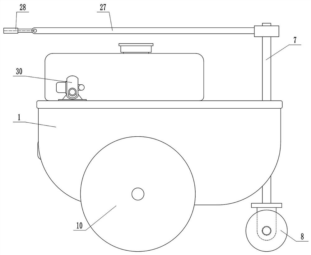
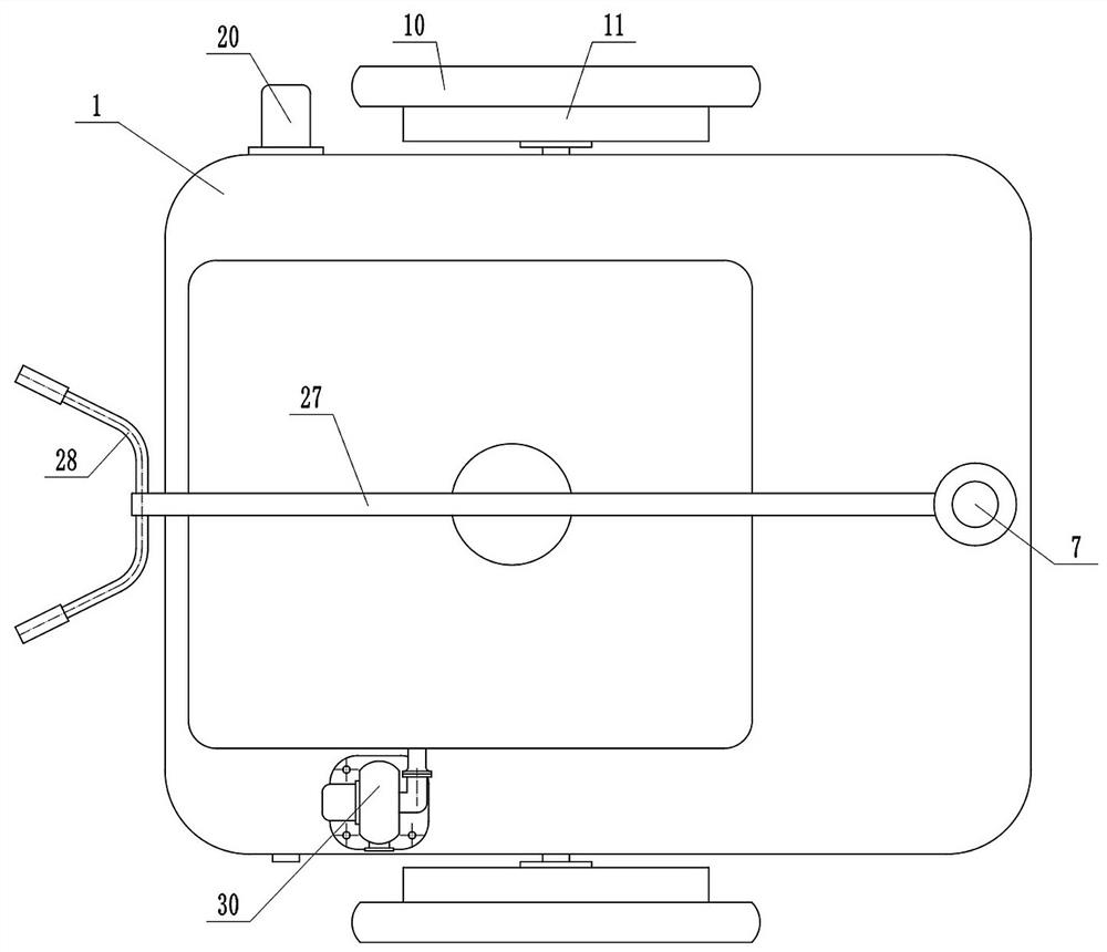
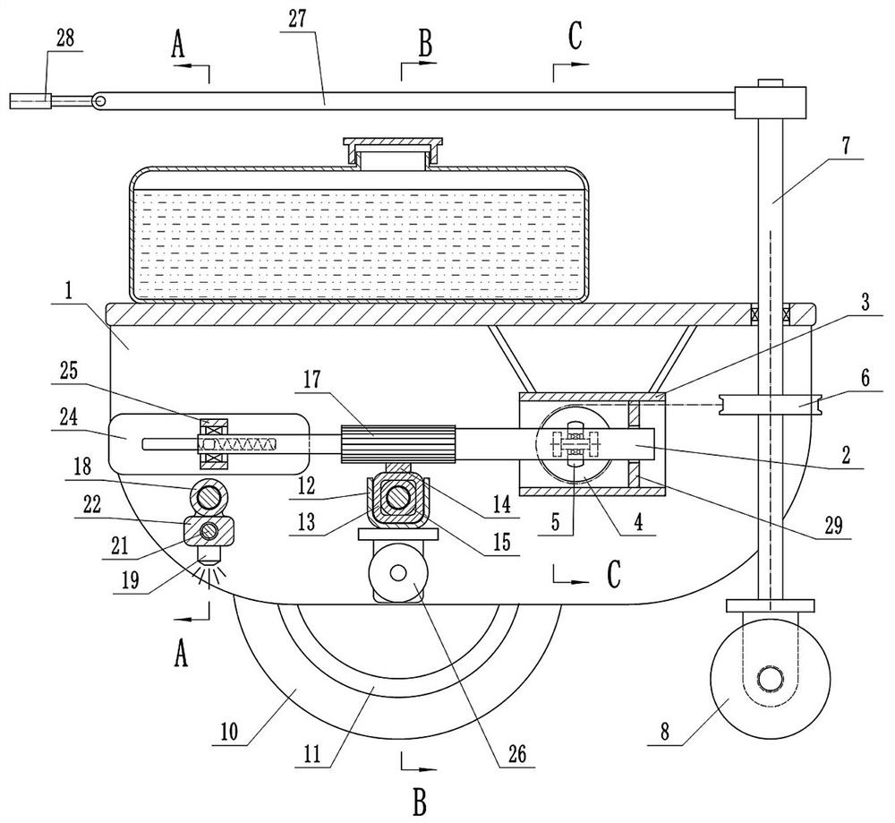
[0025] Depend on Figure 1 to Figure 8 Provided, the present invention includes a vehicle frame 1. There is a horizontal sliding shaft 2 that can move left and right in the vehicle frame 1. A guide device that controls the sliding shaft 2 to move left and right is provided at the right end of the cavity of the vehicle frame 1. Power is installed in the middle of the vehicle frame 1. device, the sprinkler actuator is installed on the left side of the frame 1;
[0026] The guide device includes a horizontal rectangular fixed shell 3, which is fixed together with a plurality of fixed shafts between the fixed shell 3 and the vehicle frame 1, the right end of the sliding shaft 2 is in the fixed shell 3, and the front and rear side plates of the fixed shell 3 There is a passive wire wheel 4 that can rotate, and there is a fri...
PUM
 Abstract
Description
Claims
Application Information