Supercharge Your Innovation With Domain-Expert AI Agents!

Design method of free-form surface reflector with robustness

A curved surface mirror and free technology, applied in the direction of optical components, optics, instruments, etc., can solve the problems of difficulty in guaranteeing the radiation output effect, weak overall design robustness, and changes in the uniformity of the radiation surface, etc., to achieve continuous The effect of increasing the difficulty of processing and reducing the processing error

Active Publication Date: 2021-08-31
INST OF DEFENSE ENG ACADEMY OF MILITARY SCI PLA CHINA +1
View PDF6 Cites 0 Cited by
  • Summary
  • Abstract
  • Description
  • Claims
  • Application Information

AI Technical Summary

Problems solved by technology

The article "Chen Jiaqi, Gu Guochao. Using the mapping method to construct free-form surface mirrors [J]. Journal of Changchun University of Science and Technology, 2013, 36(6):1-5" provides a typical free-form surface optical system to achieve uniform irradiance output Design method, this design method assumes that the light source is a point light source, and the design calculation is based on the energy distribution of the light emitted by the light source, and the mapping relationship between the light emitted by the light source and the falling point of the target surface is determined according to the law of energy conservation. There is no other means of uniform light, if If the actual light emitted by the light source differs from the data used in the design, it is difficult to guarantee the radiation output effect, and the overall design is not robust
In addition, the disadvantage of this method lies in the processing of the free-form surface. Since the overall system lacks discrete and integral homogenization systems, a small change in the parameters of the free-form surface may cause a large change in the uniformity of the irradiated surface. Processing puts forward higher requirements

Method used


Image

  • Design method of free-form surface reflector with robustness
  • Design method of free-form surface reflector with robustness
  • Design method of free-form surface reflector with robustness

Examples


Embodiment 1

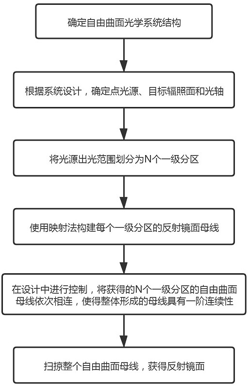
[0040] A method for designing a robust free-form surface mirror, comprising the following steps:

[0041] Step 1. Determine the structure of the free-form surface optical system, configure the positions of the light source, free-form surface and target irradiation surface in the optical system, and select the light transmission mode; for the convenience of comparison and description, embodiment 1 selects a reflective free-form surface as an illustration;

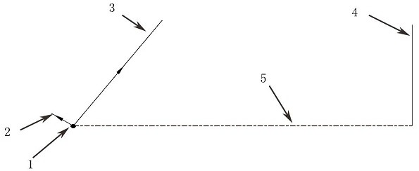
[0042] Step 2, according to system design, in embodiment 1, such as figure 2 As shown, determine the point light source A1, the target irradiation surface A4 and the optical axis A5, and determine the light output range of the light source used according to the design, and determine the marginal ray A2 and the marginal ray B3;

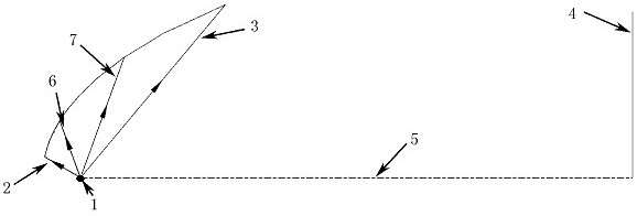
[0043] Step 3: Divide the light output range of the light source into N first-level divisions, each first-level division determines its edge rays relative to the target irradiation surface, and the ...

Embodiment 2

[0056] Embodiment 2 adopts short-arc xenon lamp light source, and the light distribution curve of light source B16 is as follows Figure 8 As shown, the light emitting area of ​​the light source B16 is bounded by the ray H17 and the ray I18, such as Figure 9 As shown, the angle range is 30°~120°. The light emitted by the light source B16 reaches the target irradiation surface B19 after being reflected by the free-form surface, forming a uniform circular spot with a size of φ300mm. The distance between the light source B16 and the target irradiation surface B19 is 500mm , the optical axis B20 is the optical axis of the system; according to the design method proposed in the present invention, the resulting free-form reflector is as Figure 10 as shown,

[0057] According to the conventional free-form surface optical system design method (refer to the article "Chen Jiaqi, Gu Guochao. Using the mapping method to construct a free-form surface mirror [J]. Journal of Changchun Univ...


PUM


Abstract

The invention provides a design method of a free-form surface reflector with robustness, and the method comprises the steps: carrying out the partitioning of a light source emergent range, guaranteeing the uniform distribution of all regions on a target surface in the design, and carrying out the superposition. The design method can effectively reduce the influence of the processing error and the inconsistent light source data on the irradiation output, and improves the robustness of the system. In addition, the first-order continuity of the free-form surface generatrix is reserved, the processing difficulty is almost not improved, and the robustness of the whole system is improved.

Description

technical field [0001] The invention relates to the technical field of non-imaging optics and lighting, in particular to the design technology of a free-form surface optical system, in particular to a design method of a robust free-form surface reflector. Background technique [0002] Compared with traditional optical components, free-form optical components have great application potential in the field of non-imaging optical systems and lighting technology because of their higher design freedom, because they can precisely control the direction of light and realize various conventional optical components. The irradiance output that the system is difficult to achieve has also gained more and more applications. [0003] The application of free-form surfaces to illumination optics enables a wide variety of irradiance outputs with tailored characteristics, but in routine applications, a uniform irradiance output is often desired. For the design of the free-form surface optical ...

Claims


Application Information

Patent Timeline
IPC IPC(8): G02B27/00
CPCG02B27/0012
Inventor 苏荣华孙云厚王吉军王雪明杨栎雷永辉张谦顾国超秦凯
Owner INST OF DEFENSE ENG ACADEMY OF MILITARY SCI PLA CHINA
Features
  • R&D
  • Intellectual Property
  • Life Sciences
  • Materials
  • Tech Scout
  • Unparalleled Data Quality
  • Higher Quality Content
  • 60% Fewer Hallucinations
Learn More