
Energy consumption type explosion-proof connector

A connector and energy-consuming technology, which is applied in the direction of connection, two-part connection device, parts of the connection device, etc., can solve problems such as hot air leakage, temperature and energy exhaustion, and explosion-proof connector structure bloated

Active Publication Date: 2021-08-31
CHINA HELON EXPLOSION PROOF ELECTRIC
View PDF7 Cites 0 Cited by
  • Summary
  • Abstract
  • Description
  • Claims
  • Application Information

AI Technical Summary

Problems solved by technology

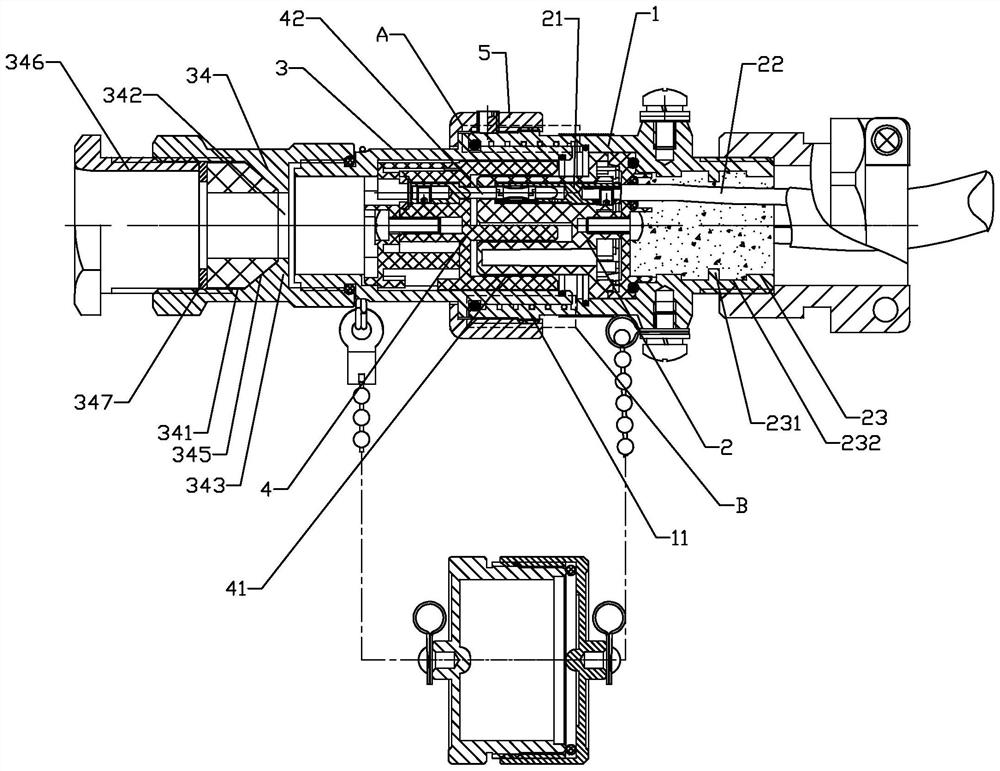
[0003] In order to solve the above problems, an explosion-proof connector has been developed, including an explosion-proof plug and an explosion-proof socket. It constitutes the connection of the power supply circuit between the instrument and the power supply. In daily use, a small explosion will often occur inside the connection between the pin and the socket due to a fault. In order to avoid the impact on the chemical work site after the explosion, the explosion-proof socket is often used It is placed on the outer periphery of the explosion-proof plug and forms an assembly gap that connects the inside with the outside world. The hot air flow formed by the explosion will move along the assembly gap, and the temperature and energy will gradually be exhausted. Therefore, in order to avoid the possibility of hot air leakage, the existing method uses Ensure that the assembly gap has sufficient length for cooling, but as the circuit load increases, simply extending the length will undoubtedly only make the structure of the explosion-proof connector too bloated

Method used


Image

  • Energy consumption type explosion-proof connector
  • Energy consumption type explosion-proof connector
  • Energy consumption type explosion-proof connector

Examples


Embodiment Construction

[0018] The technical solutions of the present invention will be clearly and completely described below in conjunction with the accompanying drawings. Apparently, the described embodiments are some of the embodiments of the present invention, but not all of them. Based on the embodiments of the present invention, all other embodiments obtained by persons of ordinary skill in the art without making creative efforts belong to the protection scope of the present invention.

[0019] In the description of the present invention, it should be noted that the terms "center", "upper", "lower", "left", "right", "vertical", "horizontal", "inner", "outer" etc. The indicated orientation or positional relationship is based on the orientation or positional relationship shown in the drawings, and is only for the convenience of describing the present invention and simplifying the description, rather than indicating or implying that the referred device or element must have a specific orientation, ...


PUM


Abstract

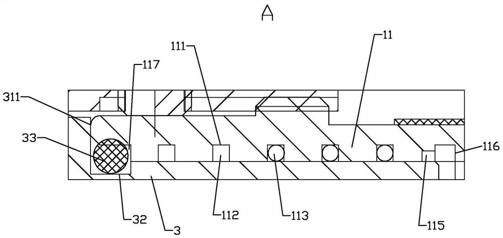
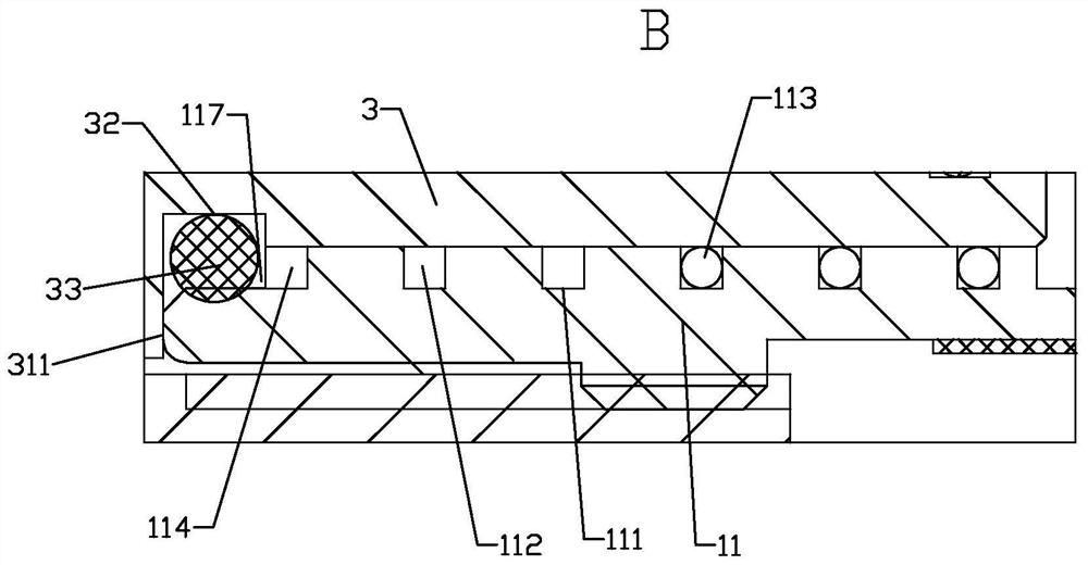
The invention relates to an energy consumption type explosion-proof connector, which comprises an explosion-proof plug, an explosion-proof socket and a locking ring, wherein the explosion-proof socket comprises a socket cylinder, a socket core body and plug bushes, the explosion-proof plug comprises a plug cylinder, a plug core body and a slot, contact pins in one-to-one correspondence with the plug bushes are fixedly arranged in the slot, the front end of the socket cylinder is provided with an assembly part in an extending manner, the locking ring locks the assembly part and the plug cylinder, a cooling groove spirally extending around the plug cylinder is formed in the inner circumference of the assembly part, a spiral main cooling channel is formed by the cooling groove and the outer circumference of the assembly part, a plurality of energy consumption steel balls rolling along the main cooling channel are arranged in the main cooling channel, one end of the main cooling channel is communicated with the outside and serves as an outer communication end of the energy consumption steel ball, and the other end is communicated with the socket cylinder and serves as an inner communication end with the opening diameter smaller than that of the energy consumption steel ball. By the adoption of the scheme, the energy consumption type explosion-proof connector is simple in structure and good in explosion-proof performance.

Description

technical field [0001] The invention relates to the field of explosion-proof power supply devices, in particular to an energy-consuming explosion-proof connector. Background technique [0002] In hazardous areas such as chemical plants, in order to ensure the normal operation of the equipment and avoid danger, a large number of instruments are often required to monitor the pipeline conditions at all times. Not only the explosion-proof design of the instruments, but also the power supply circuit for the instruments Carry out explosion-proof design. The traditional method is to put an explosion-proof bobbin around the power supply wire to realize the explosion-proof function of the power supply circuit, but this method has certain disadvantages, that is, the wire needs to be cut off when the instrument is overhauled or maintained, and then it needs to be reconnected. Many instruments not only greatly increase the workload, but also often have wrong connections. [0003] In o...

Claims


Application Information

Patent Timeline
IPC IPC(8): H01R13/533H01R13/502H01R13/639H01R24/00H05K7/20
CPCH01R13/533H01R13/502H01R13/639H01R24/00H05K7/20009Y02T10/70Y02T10/7072Y02T90/14
Inventor 谢金汉金晓鹏林哲琳张胜余张乃月
Owner CHINA HELON EXPLOSION PROOF ELECTRIC
Learn More