
Miniature filter design for antenna systems

A technology of filters and filter arrays, which can be used in waveguide-type devices, antenna grounding switch structure connections, resonators, etc., and can solve problems such as complex losses

Active Publication Date: 2021-08-31
TELEFON AB LM ERICSSON (PUBL)
View PDF13 Cites 2 Cited by
  • Summary
  • Abstract
  • Description
  • Claims
  • Application Information

AI Technical Summary

Problems solved by technology

However, such structures are rather complex to construct and are usually lossy

Method used


Image

  • Miniature filter design for antenna systems
  • Miniature filter design for antenna systems
  • Miniature filter design for antenna systems

Examples


Embodiment Construction

[0028] Before describing the exemplary embodiments in detail, it should be noted that the embodiments reside primarily in combinations of device components and processing steps related to inductive coupling methods for miniature filter design in millimeter (mm) wave applications. Accordingly, in the drawings, components have been represented by conventional symbols, where appropriate, and only those specific details that are relevant to an understanding of the embodiments are shown so as not to be obvious to those of ordinary skill in the art having the benefit of the description herein. details that obscure the disclosure. Throughout the specification, like symbols refer to like elements.

[0029] As used herein, relative terms (such as "first" and "second", "top" and "bottom", etc.) may be used only to distinguish one entity or element from another entity or element, and not necessarily No physical or logical relationship or order between such entities or elements is requir...


PUM


Abstract

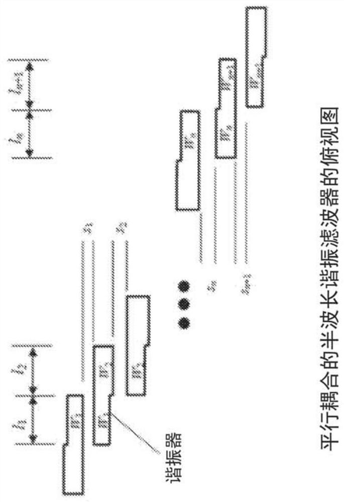
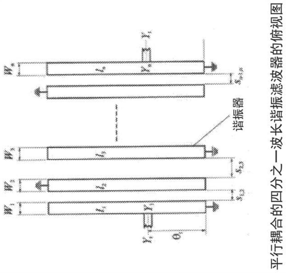
A filter and array of filters providing inductive coupling are disclosed. According to one aspect, an RF filter includes a plurality of dielectric layers with a first ground plane on one side of the dielectric layers and a second ground plane on an opposite side of the dielectric layers. One of the first and second ground planes provides an input port and one of the first and second ground planes provides an output port. Two parallel strip line resonators, lie in a first plane parallel to, and between, the first and second ground planes, the two parallel strip line resonators, having a gap there between. An inductive coupling plate in proximity to the gap, is grounded at an edge and lies in a second plane, the second plane parallel to the first plane and lying between the first plane and one of the first and second ground planes.

Description

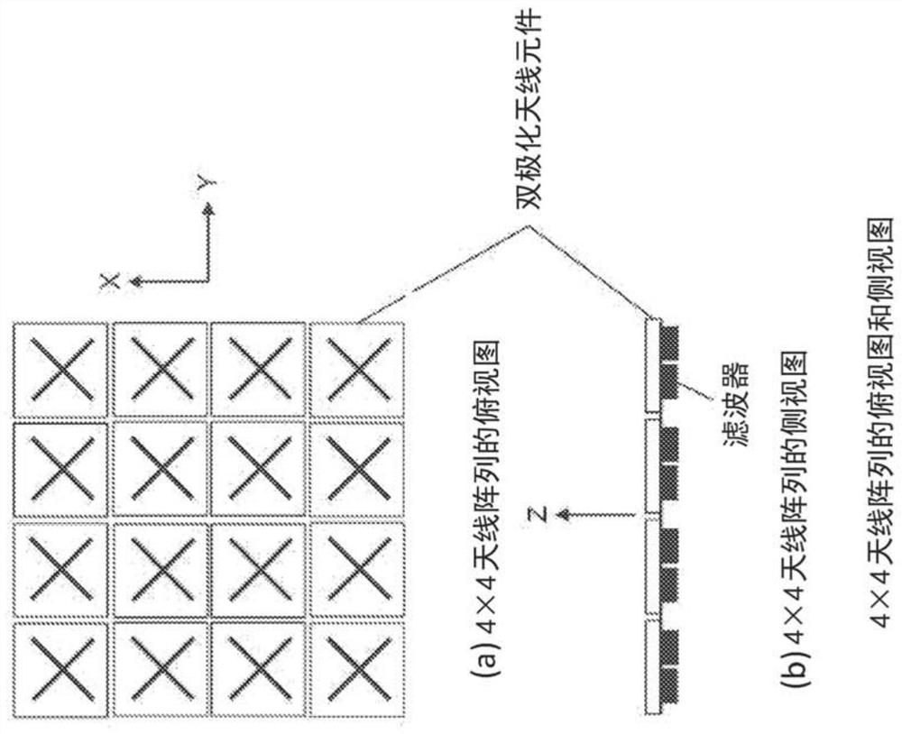
technical field [0001] The present disclosure relates to wireless communications, and in particular to filters for radio frequency (RF) front-ends in radios, and more particularly to inductive aspects of miniature filter design for fifth generation (5G) millimeter (mm) wave applications coupling arrangement. Background technique [0002] Active antenna systems (AAS) operating at frequencies of 28 gigahertz (GHz) or higher require large antenna arrays. Such antenna arrays may have 32x32 elements or 64x64 elements or even higher. figure 1 An example 4x4 antenna array with dual polarized antenna elements is shown. The array has 4 rows of 4 antenna element pairs. At high frequencies, the antenna size becomes very small. For example, at 28GHz, one antenna element size may be about 5mm x 5mm. Each antenna element is followed by a filter. Therefore, the filter should also be very small, and tiny filters may be required, especially in the x-y dimension. Multilayer low tempera...

Claims


Application Information

Patent Timeline
Patent Type & Authority Applications(China)
IPC IPC(8): H01P1/203
CPCH01P1/20345H01P1/20H01P7/08H01Q1/50
Inventor 简春云周蜜
Owner TELEFON AB LM ERICSSON (PUBL)
Learn More