
A comprehensive escape system for underground pipe gallery and its construction and operation method

An escape system and underground pipe gallery technology, applied in life-saving equipment, respiratory protection containers, advanced technologies, etc., can solve the problems of long pipe gallery length, unreliable route, adverse effects of personnel escape, etc., to improve the success rate and survival rate The effect of the reliability of the rate, escape routes and equipment, and the variety of escape methods

Active Publication Date: 2022-07-08
SHANGHAI ELECTRICAL APPLIANCES RES INSTGROUP +1
View PDF6 Cites 0 Cited by
  • Summary
  • Abstract
  • Description
  • Claims
  • Application Information

AI Technical Summary

Problems solved by technology

However, due to the long length of the pipe corridor and the small space, people often do not know where they are and which escape exit is closest to them, and it is very easy to escape to an escape exit far away from them.
[0007] 3. The planning method of the escape route is single, which is to operate by human memory, and there are too many unreliability in the planning of the route
[0008] 4. The system is relatively isolated, and often only meets the needs of opening on the spot when escaping, without forming automatic judgment, automatic opening and other operations, the degree of intelligence is not high, and problems are prone to occur
[0009] 5. When a dangerous situation occurs, the fire system will automatically explode the ultra-fine dry powder, which will adversely affect the escape of personnel, and it is very easy to suffocate personnel.

Method used


Image

  • A comprehensive escape system for underground pipe gallery and its construction and operation method
  • A comprehensive escape system for underground pipe gallery and its construction and operation method
  • A comprehensive escape system for underground pipe gallery and its construction and operation method

Examples


Embodiment Construction

[0036] In order to make the present invention more obvious and comprehensible, preferred embodiments are described in detail below with reference to the accompanying drawings.

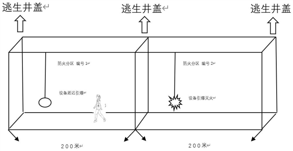
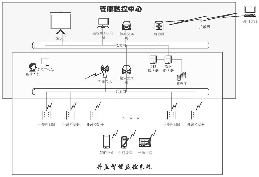
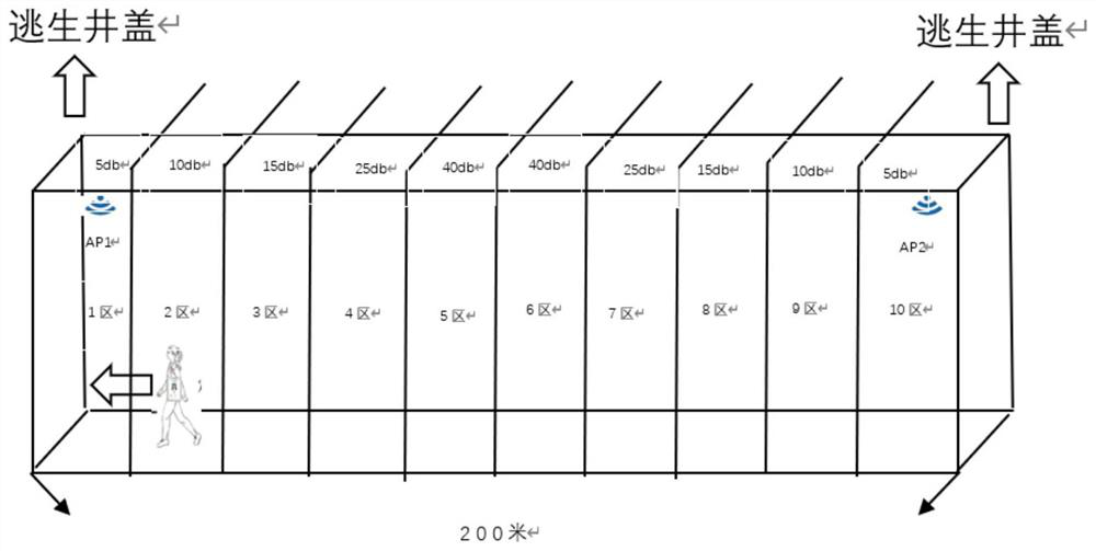
[0037] like Figure 5 As shown, an underground pipe gallery comprehensive escape system of the present invention includes a host computer, an environmental monitoring system, a wireless AP system, a fire protection system and a manhole cover intelligent monitoring system. The environmental monitoring system is used to monitor the environmental parameter signal in the pipe gallery and send it to the host computer, and the host computer judges whether a disaster occurs according to the received environmental parameter signal. The wireless AP system is used to locate the personnel and send the positioning signal to the upper computer. The fire protection system is used to receive the personnel positioning signal sent by the host computer and close the control loop in the fire compartment where the person...


PUM


Abstract

The invention discloses a comprehensive escape system for an underground pipe gallery and a construction and operation method thereof. The pipe gallery is divided into a plurality of fire compartments, and each fire compartment is equidistantly divided into a plurality of districts; The signal is monitored and the corresponding data is output to the host computer; the hand-held terminal of the personnel is connected to the wireless AP device in the pipe gallery to determine the number of districts in the fire zone where the personnel are located; when a fire occurs, the host computer will be nearby according to the personnel positioning signal. Call the manhole cover signals on both sides of the fire compartment where the personnel are located, and open the manhole cover. Through the mutual linkage of various subsystems in the pipe gallery, the real-time status of each system can be dynamically read, the data of each system can be fully utilized, and the most efficient escape route can be provided for the operation and maintenance personnel in real time, thus ensuring the operation of the pipe gallery. In the event of danger, maintenance personnel can escape from the underground space in a timely and efficient manner to ensure personal safety.

Description

technical field [0001] The invention relates to an underground pipe gallery comprehensive escape system and a construction and operation method thereof. Background technique [0002] Because the integrated pipe gallery is built underground, compared with the construction environment on the ground, the underground environment is relatively harsh, the system equipment is easily affected by the environment such as closed and dark, and the interval between each fire compartment is also large. Often in the event of a sudden accident, some of the escape equipment is damaged due to long-term failure to start, which delays the time for people to escape. Therefore, in the construction and later operation and maintenance management of the pipe gallery, the existence of a reliable escape system can greatly improve the survival rate of personnel. [0003] Nowadays, most of the escape systems used in underground pipe corridors use escape manhole covers. The control of manhole covers is ...

Claims


Application Information

Patent Timeline
Patent Type & Authority Patents(China)
IPC IPC(8): A62B31/00
CPCA62B31/00Y02D30/70
Inventor 吴颉唐晓俊姬卫东童巍戚琛琛
Owner SHANGHAI ELECTRICAL APPLIANCES RES INSTGROUP
Learn More