Tubular metal part inner and outer cleaning and drying device
A technology for metal parts and drying devices, which is applied in the direction of drying, dryer, drying gas arrangement, etc. It can solve the problems of difficult manual cleaning, time-consuming and labor-intensive tubular metal parts, and inability to clean parts, so as to improve cleaning efficiency and facilitate Cleaning, the effect of realizing the function
- Summary
- Abstract
- Description
- Claims
- Application Information
AI Technical Summary
Problems solved by technology
Method used
Image

Examples
Embodiment Construction
[0029] The technical solutions in the embodiments of the present invention will be clearly and completely described below in conjunction with the embodiments of the present invention. Apparently, the described embodiments are only some of the embodiments of the present invention, not all of them. Based on the embodiments of the present invention, all other embodiments obtained by persons of ordinary skill in the art without creative efforts fall within the protection scope of the present invention.
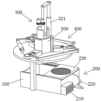
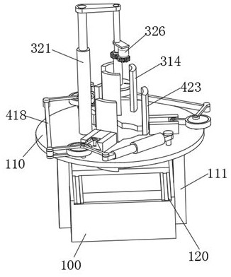
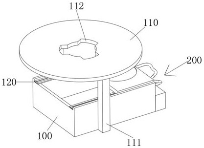
[0030] see Figure 1-8 As shown, a kind of internal and external cleaning and drying device for tubular metal parts includes a liquid receiving box 100, the top of the liquid receiving box 100 is fixedly connected with a circular receiving plate 110, and one end of the liquid receiving box 100 is fixedly connected with a drying module 200, the circular The top of the shaped receiving tray 110 is provided with an inner cleaning module 300, the inner cleaning module 300 includes an ...
PUM
 Abstract
Description
Claims
Application Information
PatSnap Eureka turns technology decisions into work you can execute. Powered by our Innovation Knowledge Graph, it runs expert workflows across engineering, life sciences, materials and intellectual property. Get your review-ready output in minutes.


