Punching die waste discharging mechanism and punching die thereof

A punching die and waste technology, applied in the direction of punching tools, manufacturing tools, forming tools, etc., can solve the problems of inability to effectively prolong the service life of punching, cumbersome replacement of punching worktables, protection of punches and punching dies, etc. The effect of reducing the risk of fracture failure, increasing service life and reducing fatigue stress

Pending Publication Date: 2021-09-03
昆山日腾精密模具科技有限公司
View PDF1 Cites 2 Cited by
  • Summary
  • Abstract
  • Description
  • Claims
  • Application Information

AI Technical Summary

Problems solved by technology

[0003] The above-mentioned device is a common stamping die structure in the prior art, but there are still obvious defects in the above-mentioned workpiece stamping device during use: 1. The above-mentioned device improves the wear resistance of the punching head by setting a wear-resistant layer on the surface of the punching head However, the punching of the fixed seat has not been subjected to corresponding wear-resistant treatment. In the actual production process, the continuous punching operation makes the punching head repeatedly cooperate with the punching hole, so that the component to be punched is constantly in contact with the punching head and the punching hole. Hole extrusion will easily lead to mold wear or even crack failure in the long run, and the above-mentioned device does not effectively protect the punch and punching die; 2. The above-mentioned device and the punch and punch in the prior art usually adopt a fixed fit method, This kind of matching method leads to repeated cooperation between the same punching hole and the punching head. Since the structure of the punching head is easy to replace, and the replacement of the workbench where the punching hole is located is relatively cumbersome, the existing technology cannot effectively prolong the service life of the punching hole.

Method used


Image

  • Punching die waste discharging mechanism and punching die thereof
  • Punching die waste discharging mechanism and punching die thereof
  • Punching die waste discharging mechanism and punching die thereof

Examples


Embodiment

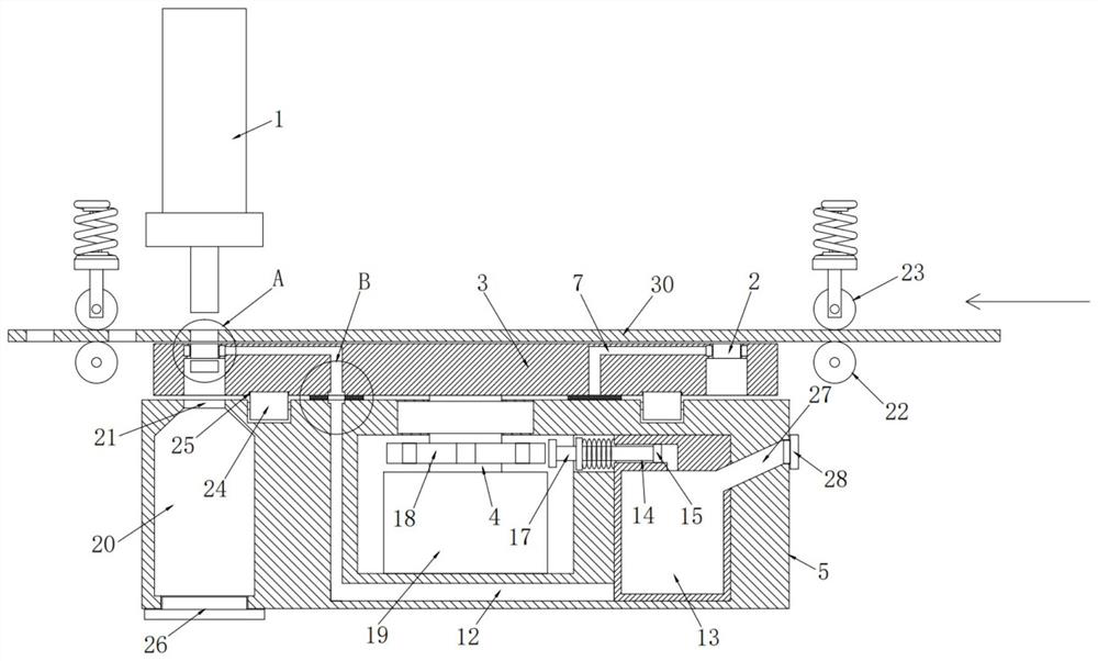
[0028] see Figure 1-7 , the present invention provides a technical solution:

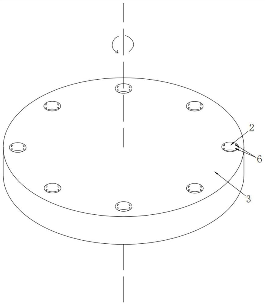
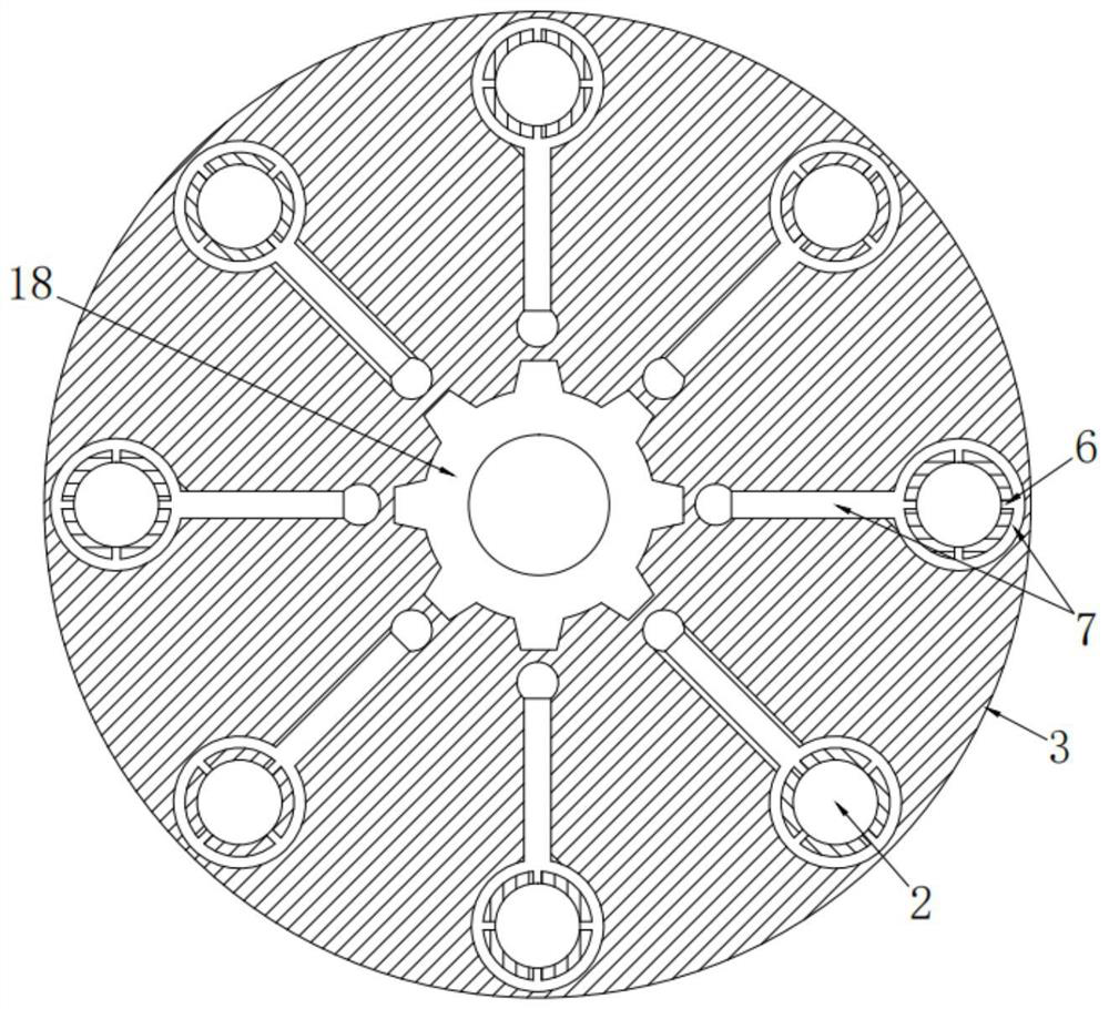
[0029] A stamping die waste discharge mechanism and its stamping die, including a punch 1, the punch 1 cooperates with several discharge holes 2 intermittently, and the punch 1 cooperates with the discharge holes 2 to punch holes in the punching continuous conveying parts 30 , a number of discharge holes 2 are arranged in a circular array on the rotary table 3, and the rotation of the rotary table 3 makes the different discharge holes 2 cooperate with the punch 1 in turn, and the rotary table 3 is installed on the discharge fixed by the rotating shaft 4. On the seat 5, the rotation of the rotary table 3 is driven by the rotation of the rotating shaft 4;

[0030] There are stamping oil release holes 6 in several discharge holes 2, and the stamping oil release holes 6 communicate with the oil inlet hole 8 at the far end through the oil supply channel 7 opened in the rotary table 3, and the oil inlet...


PUM


Abstract

The invention provides a punching die waste discharging mechanism and a punching die thereof. The punching die waste discharging mechanism comprises a punch, the punch is in intermittent fit with multiple discharging holes, the multiple discharging holes are formed in a rotary workbench in an annular array manner, and the rotary workbench is movably installed on a discharging fixing base through a rotating shaft. Punching oil release holes are formed in the multiple discharging holes, the end, away from a one-way air inlet piston, of an extrusion connecting rod movably abuts against an oil pumping protruding rotary disc, and the oil pumping protruding rotary disc is fixedly installed on the rotating shaft of the rotary workbench. The arrangement of the rotary workbench is adopted, different punching holes alternately cooperates with the punch for punching operation, the punching oil release holes are formed in the punching holes, punching oil released by the punching oil release holes is bidirectionally smeared in each cooperation process of the punch and the punching holes, fatigue stress between dies is greatly reduced, the die is prevented from being damaged in the high-strength machining process, and the service life of the die is further prolonged.

Description

technical field [0001] The invention relates to the technical field of stamping machinery, in particular to a stamping die waste discharge mechanism and the stamping die. Background technique [0002] A workpiece punching device with the application number of "CN201620749310.8" in the prior art includes a support base plate, an L-shaped support is provided on the upper end of the support base plate, and a high-speed stamping cylinder is provided on the horizontal section of the L-shaped support. The output shaft of the high-speed stamping cylinder is located inside the stamping cavity of the upper fixing seat, the output shaft of the high-speed stamping cylinder is connected with the stamping rod, and a return spring is arranged between the stamping rod and the upper fixing seat, and the bottom of the stamping rod is connected to the stamping rod. A wear-resistant layer is provided on the surface of the stamping head, a lower fixing seat is provided on the support base and d...

Claims


Application Information

Patent Timeline
Patent Type & Authority Applications(China)
IPC IPC(8): B21D28/34B21D28/26B21D28/04B21D37/18
CPCB21D28/34B21D28/26B21D28/04B21D37/18
Inventor 王卫民朱叶飞许佳辉苗喜民杜振飞
Owner 昆山日腾精密模具科技有限公司
Why Eureka
Try Eureka