Welding tool facilitating angle positioning for fan blade machining

An angle positioning and fan blade technology, which is applied in welding equipment, auxiliary welding equipment, metal processing equipment, etc., can solve the problems of inconvenient adjustment of fan blade inclination angle, inconvenient fan blade clamping and positioning, and inability to cool in time

Inactive Publication Date: 2021-09-03
重庆冰柠智能科技有限公司
View PDF0 Cites 3 Cited by
  • Summary
  • Abstract
  • Description
  • Claims
  • Application Information

AI Technical Summary

Problems solved by technology

[0004] The purpose of the present invention is to provide a welding tool for fan blade processing that is convenient for angular positioning, so as to solve the problem that the existing welding tool for fan blade processing proposed in the background technology is not convenient for clamping the fan blade during the welding process. It is not convenient to adjust the inclination angle of the fan blade, and it cannot be cooled in time after welding, which is prone to welding deformation.

Method used


Image

  • Welding tool facilitating angle positioning for fan blade machining
  • Welding tool facilitating angle positioning for fan blade machining
  • Welding tool facilitating angle positioning for fan blade machining

Examples


Embodiment Construction

[0027] The technical solutions in the embodiments of the present invention will be clearly and completely described below in conjunction with the accompanying drawings in the embodiments of the present invention. Obviously, the described embodiments are only some of the embodiments of the present invention, not all of them. Based on The embodiments of the present invention and all other embodiments obtained by persons of ordinary skill in the art without making creative efforts belong to the protection scope of the present invention.

[0028] In the description of the present invention, unless otherwise stated, the meaning of "plurality" is two or more; the terms "upper", "lower", "left", "right", "inner", "outer" , "front end", "rear end", "head", "tail", etc. indicate the orientation or positional relationship based on the orientation or positional relationship shown in the drawings, and are only for the convenience of describing the present invention and simplifying the desc...


PUM


Abstract

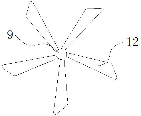
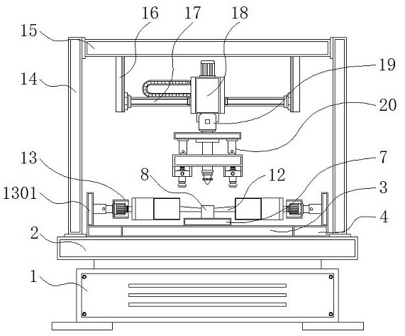
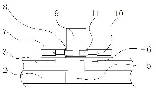
The invention discloses a welding tool facilitating angle positioning for fan blade machining, and relates to the technical field of fan blade machining. The welding tool comprises a machine body, an adjusting positioning mechanism and a welding mechanism. A workbench is fixed above the machine body, a chassis is mounted above the workbench, and a convex plate is fixed to the outer side of the chassis. An electric push rod is installed in the middle of the interior of the chassis, a push plate is fixed above the electric push rod, a bearing plate is installed above the push plate, the bearing plate is located on the upper side of the chassis, a shaft hole is formed in the middle of the interior of the bearing plate, a fan blade rotating shaft is arranged in the shaft hole, and fan blades are arranged on the outer side of the fan blade rotating shaft. Hydraulic rods are installed on the two sides of the interior of the bearing plate. The device has the beneficial effects that the device is provided with the bearing plate, the shaft hole in the middle of the interior of the bearing plate facilitates arrangement of the fan blade rotating shaft, and meanwhile, the bearing plate has a certain height so that the fan blades on the outer side of the fan blade rotating shaft can be suspended, and the upper sides and the lower sides of the fan blades can be conveniently positioned and fixed.

Description

technical field [0001] The invention relates to the technical field of fan blade processing, in particular to a welding tool for fan blade processing which is convenient for angle positioning. Background technique [0002] Fan refers to a device used to generate wind to keep cool in hot weather. The electric fan is a device driven by electricity to generate air flow. The fan inside is energized and then rotates into natural wind to achieve the effect of enjoying the cool. Fan blades are an important part of a fan and are used to turn the airflow that forms the wind. In the process of fan processing, fan blades need to be welded, so welding tools are required. [0003] The existing welding tool for fan blade processing is inconvenient to clamp and position the fan blade, and it is inconvenient to adjust the inclination angle of the fan blade during the welding process. Moreover, it cannot be cooled in time after welding, and welding deformation is prone to occur , for this...

Claims


Application Information

Patent Timeline
Patent Type & Authority Applications(China)
IPC IPC(8): B23K37/047
CPCB23K37/047
Inventor 蒲自强许淑婷赖锦丽
Owner 重庆冰柠智能科技有限公司
Why Eureka
Try Eureka