Clamp and operation table

A technology of operating table and fixture, applied in the direction of work table, manufacturing tool, workpiece clamping device, etc., can solve the problem of low core efficiency, and achieve the effect of improving efficiency and reducing labor intensity

Pending Publication Date: 2021-09-03
XIAOGAN HUAGONG GAOLI ELECTRONICS
View PDF0 Cites 0 Cited by
  • Summary
  • Abstract
  • Description
  • Claims
  • Application Information

AI Technical Summary

Problems solved by technology

[0004] The purpose of the present invention is to provide a fixture and an operating table to solve the problem of low efficiency of the existing fixture to clamp the core body after printing glue assembly

Method used


Image

  • Clamp and operation table
  • Clamp and operation table
  • Clamp and operation table

Examples


Embodiment Construction

[0028] A fixture and an operating table proposed by the present invention will be further described in detail below in conjunction with the accompanying drawings and specific embodiments. The advantages and features of the present invention will become clearer from the following description. It should be noted that all the drawings are in a very simplified form and use imprecise scales, and are only used to facilitate and clearly assist the purpose of illustrating the embodiments of the present invention.

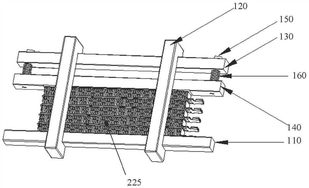
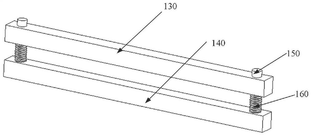
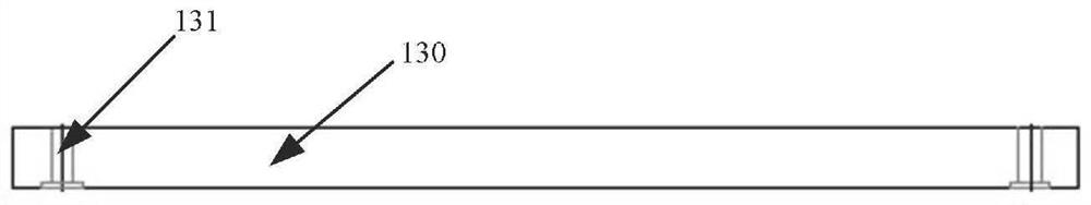
[0029] refer to figure 1 , figure 2 , image 3 and Figure 4 , figure 1 It is a schematic structural view of the core body of the clamp clamping the PTC heater in the embodiment of the present invention, figure 2 It is a structural schematic diagram of the first elastic block 130, the second elastic block 140, the fastener 150 and the elastic member 160 in the clamp in the embodiment of the present invention, image 3 is a cross-sectional view of the first elastic b...


PUM


Abstract

The invention provides a clamp and an operation table. The clamp is used for clamping a workpiece and comprises a check block, a C-shaped clamp, a first elastic block, a second elastic block, a fastening piece and an elastic piece, a mounting hole is formed in the first elastic block, and the fastening piece penetrates through the mounting hole to be in threaded connection with the second elastic block. The elastic piece is arranged between the first elastic block and the second elastic block and used for enabling the first elastic block and the second elastic block to be away from each other, the check block is located on the side, away from the first elastic block, of the second elastic block, and a workpiece is located between the check block and the second elastic block. The first elastic block, the second elastic block, the fastening piece, the elastic piece, the workpiece and the check block are clamped in the C-shaped clamp, and the C-shaped clamp is used for limiting the first elastic block and the second elastic block to be away from each other. The workpiece clamping efficiency of the clamp can be improved.

Description

technical field [0001] The invention relates to the technical field of PTC heater processing, in particular to a fixture and an operating table. Background technique [0002] PTC heaters are widely used in electric vehicles due to their stable performance, rapid temperature rise, and less influence from power supply voltage fluctuations. After the core body of the PTC heater is printed and assembled, it must be clamped and then enter the oven for high temperature curing. At present, the jig for clamping the core of the PTC heater assembled by printing glue usually pushes the slider in the jig to clamp the core of the PTC heater by tightening the screws in the jig. This kind of jig has complex operations and low production efficiency. The problem. [0003] Therefore, it is necessary to improve the existing clamps so as to improve the efficiency of clamping the core body after printing and assembling. Contents of the invention [0004] The purpose of the present invention...

Claims


Application Information

Patent Timeline
Patent Type & Authority Applications(China)
IPC IPC(8): B25B11/00B25H1/08
CPCB25B11/00B25H1/08
Inventor 甘庆文陈剑斌
Owner XIAOGAN HUAGONG GAOLI ELECTRONICS
Why Eureka
Try Eureka