
Silica gel welding equipment

A technology of welding equipment and silica gel, which is applied in the field of silica gel welding equipment, can solve the problems of unstable use, safety, and hidden dangers, and achieve the effect of convenient temperature, time, length intelligent control, and high degree of automation

Pending Publication Date: 2021-09-03
DONGGUAN POLYTECHNIC
View PDF8 Cites 1 Cited by
  • Summary
  • Abstract
  • Description
  • Claims
  • Application Information

AI Technical Summary

Problems solved by technology

[0002] After the silicone strip is produced, it is generally processed into a long strip or a long columnar structure. According to the needs of the market, it is necessary to cut the long strip or long columnar silicone strip into segments, and then use the bonding equipment to glue the segmental Silicone strips are bonded to form a ring structure to meet the needs of use. However, the existing silica gel strips need to be cut manually, and the bonding process also requires manual butt bonding and pressing. On the one hand, cutting The efficiency is low, and the control of the cutting length is unstable. On the other hand, during the bonding process, the manual bonding and pressing efficiency is low, which cannot effectively improve the processing efficiency of the silicone strips. Poor, the production quality of the silicone ring is different, and the use effect is unstable. At the same time, there are still hidden dangers in the manual processing, and the production and processing safety is low.

Method used


Image

  • Silica gel welding equipment
  • Silica gel welding equipment
  • Silica gel welding equipment

Examples


Embodiment Construction

[0024] In order to facilitate the understanding of the present invention, the present invention will be described more fully below with reference to the associated drawings. Preferred embodiments of the invention are shown in the accompanying drawings. However, the present invention can be embodied in many different forms and is not limited to the embodiments described herein. On the contrary, these embodiments are provided to make the understanding of the disclosure of the present invention more thorough and comprehensive.

[0025] It should be noted that when an element is referred to as being “fixed” to another element, it can be directly on the other element or there can also be an intervening element. When an element is referred to as being "connected to" another element, it can be directly connected to the other element or intervening elements may also be present.

[0026] Unless otherwise defined, all technical and scientific terms used herein have the same meaning as...


PUM


Abstract

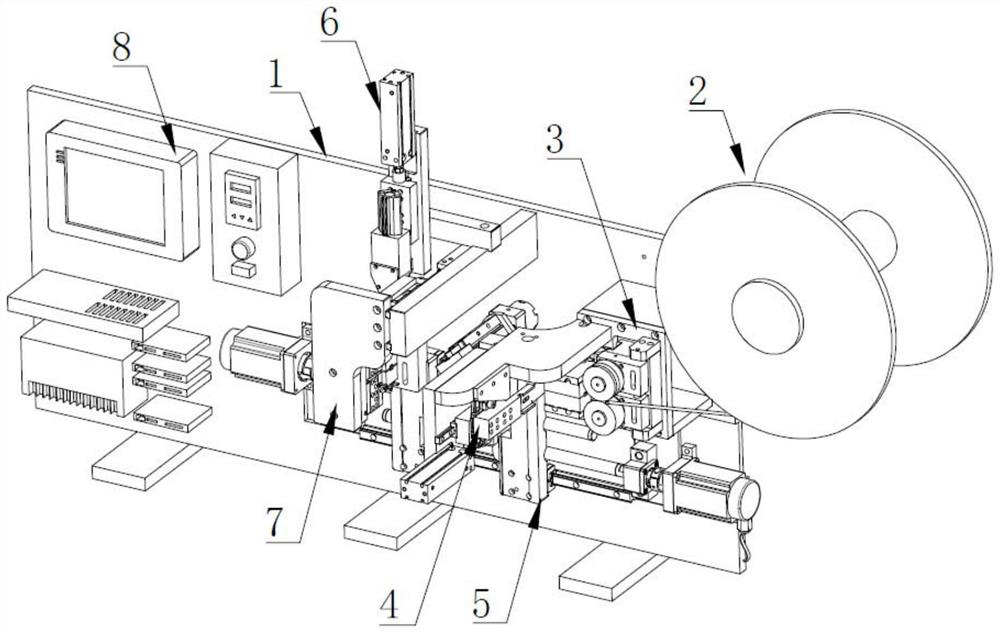
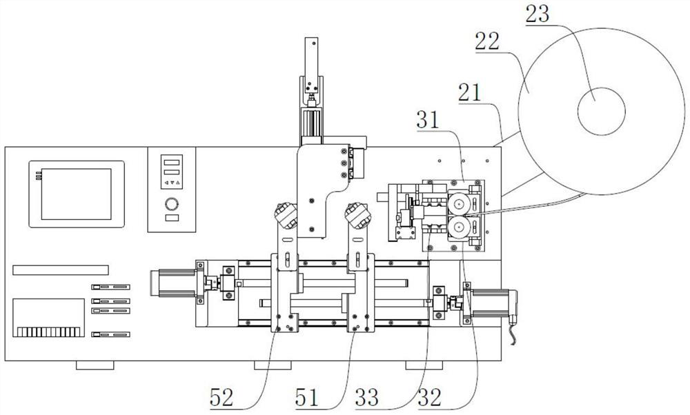
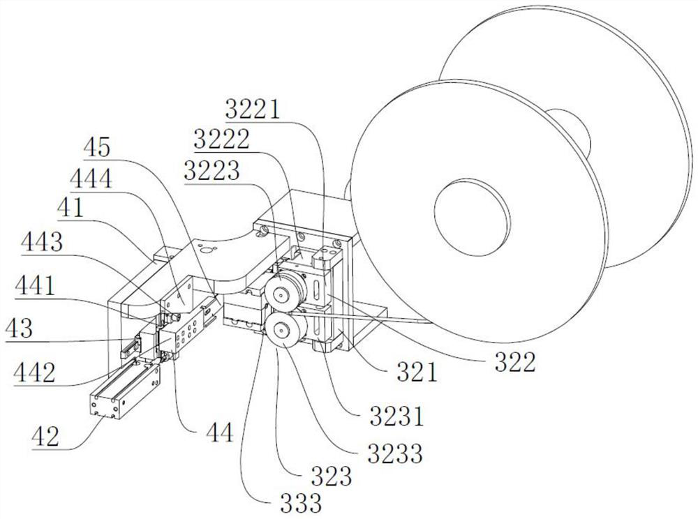
The invention relates to the technical field of silica gel welding, in particular to silica gel welding equipment. The equipment comprises a machine frame, a discharging mechanism arranged at one side of the machine frame, a material guiding mechanism arranged on the machine frame, a material cutting mechanism arranged on the material guiding mechanism, a material clamping and pulling mechanism arranged on the machine frame, a gluing mechanism arranged on the machine frame and located above the material clamping and pulling mechanism, a welding mechanism arranged on the machine frame and located at one side of the material clamping and pulling mechanism, and a controller installed on the machine frame. Full-automatic feeding is adopted, clamping and pulling are matched with rotation after feeding, the head end and the tail end of a cut-off silica gel strip are clamped through a first clamping device and a second clamping device, the silica gel strip is rotated after being clamped, the two ends corresponding to the head end and the tail end are glued through the gluing mechanism, and a silica gel ring is formed through welding of the welding mechanism after gluing is completed. The overall automation degree is high.

Description

technical field [0001] The invention relates to the technical field of silica gel welding, in particular to a silica gel welding equipment. Background technique [0002] After the silicone strip is produced, it is generally processed into a long strip or a long columnar structure. According to the needs of the market, it is necessary to cut the long strip or long columnar silicone strip into segments, and then use the bonding equipment to glue the segmental Silicone strips are bonded to form a ring structure to meet the needs of use. However, the existing silica gel strips need to be cut manually, and the bonding process also requires manual butt bonding and pressing. On the one hand, cutting The efficiency is low, and the control of the cutting length is unstable. On the other hand, during the bonding process, the manual bonding and pressing efficiency is low, which cannot effectively improve the processing efficiency of the silicone strips. Poor, the production quality of...

Claims


Application Information

Patent Timeline
IPC IPC(8): B29C65/52B29C65/74B29C65/18B29C65/78
CPCB29C65/52B29C65/74B29C65/18B29C65/7841B29C65/7861B29C66/9141B29C66/944B29C66/95
Inventor 唐先军彭小军邓丽娟李国臣李英唐方红闫晨雨
Owner DONGGUAN POLYTECHNIC
Learn More